Booster braking device for automobile

A technology of automobile braking and braking force, applied in the direction of braking transmission, brakes, vehicle components, etc., can solve the problems of driving safety impact, failure to provide braking boost, and braking system cannot obtain braking boost, etc., to achieve flexible The effect of simple and direct control and mechanical machinery and convenient maintenance

Inactive Publication Date: 2007-10-24
SHANGHAI HUAPU AUTOMOBILE CO LTD
View PDF0 Cites 6 Cited by
  • Summary
  • Abstract
  • Description
  • Claims
  • Application Information

AI Technical Summary

Problems solved by technology

The vacuum state depends on the working of the engine, if the engine is not working, the brake system cannot get brake boost
Because hybrid vehicles often turn off the engine in order to save fuel, and are in the state of canceling the engine idling condition, it will not be able to provide brake booster at this time, which will affect driving safety.

Method used


Image

  • Booster braking device for automobile
  • Booster braking device for automobile
  • Booster braking device for automobile

Examples


Embodiment Construction

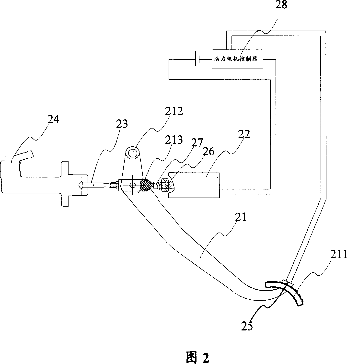
[0030] Please refer to FIG. 2 , which is a structural principle diagram of the first embodiment of the present invention.

[0031] As shown in FIG. 2 , the automobile brake booster system includes a brake pedal 21 , a booster motor 22 , a brake master cylinder 24 , a pressure sensor 25 and a booster motor controller 28 .

[0032] One end of the brake pedal 21 is a foot pedal 211 for receiving the operating force, and the other end is a fixed rotating shaft 212; the brake pedal 21 also has an output end 213, which is hinged with the brake master cylinder push rod 23. When the pedal 212 of the moving pedal 21 is energized, its output end 213 can rotate around the fixed rotating shaft 212, and energizes on the push rod 23 of the brake master cylinder.

[0033] The rotating shaft of the booster motor 22 is fixedly connected with the nut 26 , and meanwhile, the nut 26 cooperates with the lead screw 27 as a screw pair. Therefore, when the booster motor 22 rotates, the nut 26 also r...


PUM


Abstract

The invention relates to a vehicle brake assistant system that comprises the brake pedal, master cylinder, assistant generator that pushes the master cylinder push rod to provide assistant force, with the said assistant generator rotary shaft fixed with the nut, and the nut with the lead screw that directly push the master cylinder. The lead screw and the master cylinder are linked in loose joint by ball hinges. The said brake pedal installs with pressure sensor to inspect the existence of the brake force to control brake assistance. It will not be affected by the working conditions of the vehicle engine.

Description

technical field [0001] The invention relates to automobile technology, in particular to an automobile booster brake master cylinder. Background technique [0002] With the continuous reduction of oil resources, the development of fuel-efficient and environment-friendly hybrid vehicles has become a hot spot in the automotive industry. A hybrid vehicle is an electric vehicle, which uses a traditional internal combustion engine and an electric motor as a power source, and drives the vehicle through a mixture of two systems of heat energy and electric energy. The biggest feature of the hybrid power system is the complementary working mode of oil and electric engines. When starting or running at a low speed, the car only relies on electric power to drive. At this time, the gasoline engine is turned off, and the fuel consumption of the vehicle is zero; The motor starts at the same time and begins to output power; when the vehicle brakes, the hybrid system can convert kinetic ene...

Claims


Application Information

Patent Timeline
Patent Type & Authority Applications(China)
IPC IPC(8): B60T13/74
Inventor 刘昕李峰
Owner SHANGHAI HUAPU AUTOMOBILE CO LTD
Why Eureka
Try Eureka