Middle-high-temperature solar vacuum heat-collecting tube glass end cap packaging structure and fabrication technology

A vacuum heat collector tube and packaging structure technology, applied in the field of solar thermal utilization, can solve the problems of heat loss of metal end caps, low lead sealing temperature, etc., and achieve the effects of overcoming large heat loss, improving use reliability, and reliable connection and sealing

Inactive Publication Date: 2007-10-31
中金盛唐新能源科技(北京)有限公司
View PDF1 Cites 24 Cited by
  • Summary
  • Abstract
  • Description
  • Claims
  • Application Information

AI Technical Summary

Problems solved by technology

[0005] The technical problem to be solved by the present invention is to overcome the technical defects of the above-mentioned low lead sealing temperature and heat loss of metal end ca

Method used


Image

  • Middle-high-temperature solar vacuum heat-collecting tube glass end cap packaging structure and fabrication technology
  • Middle-high-temperature solar vacuum heat-collecting tube glass end cap packaging structure and fabrication technology
  • Middle-high-temperature solar vacuum heat-collecting tube glass end cap packaging structure and fabrication technology

Examples


Embodiment 1

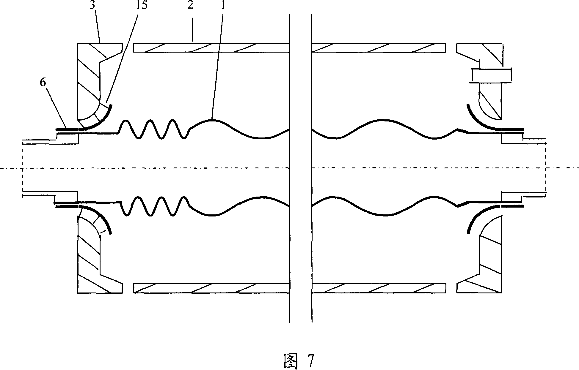
[0030] The iron-nickel alloy kovar 6 is subjected to hydrogen-protected high-temperature atomization treatment after stretching, so that the chemical bonds on the atomized layer of the iron-nickel alloy remain compatible with the high boron glass. The high-boron glass frit melted at high temperature in the furnace is poured into the mold cavity. Before the glass frit is poured, the spherical tubular iron-nickel alloy kovar piece 6 is placed in the mold, preheated together with the mold, and then the droplet is pressed into shape. After discharge, heat treatment according to the glass operating regulations, annealing and stress relief, and then use it as a component for spare use. When making solar vacuum heat collecting tubes, glass end caps 3 are placed between the inner and outer tubes at both ends. One end of the iron-nickel alloy kovar piece 6 welded on the glass end cover 3 is argon-arc welded with the metal inner tube 1 and the pipe joint 4 . In order to be suitable for...

Embodiment 2

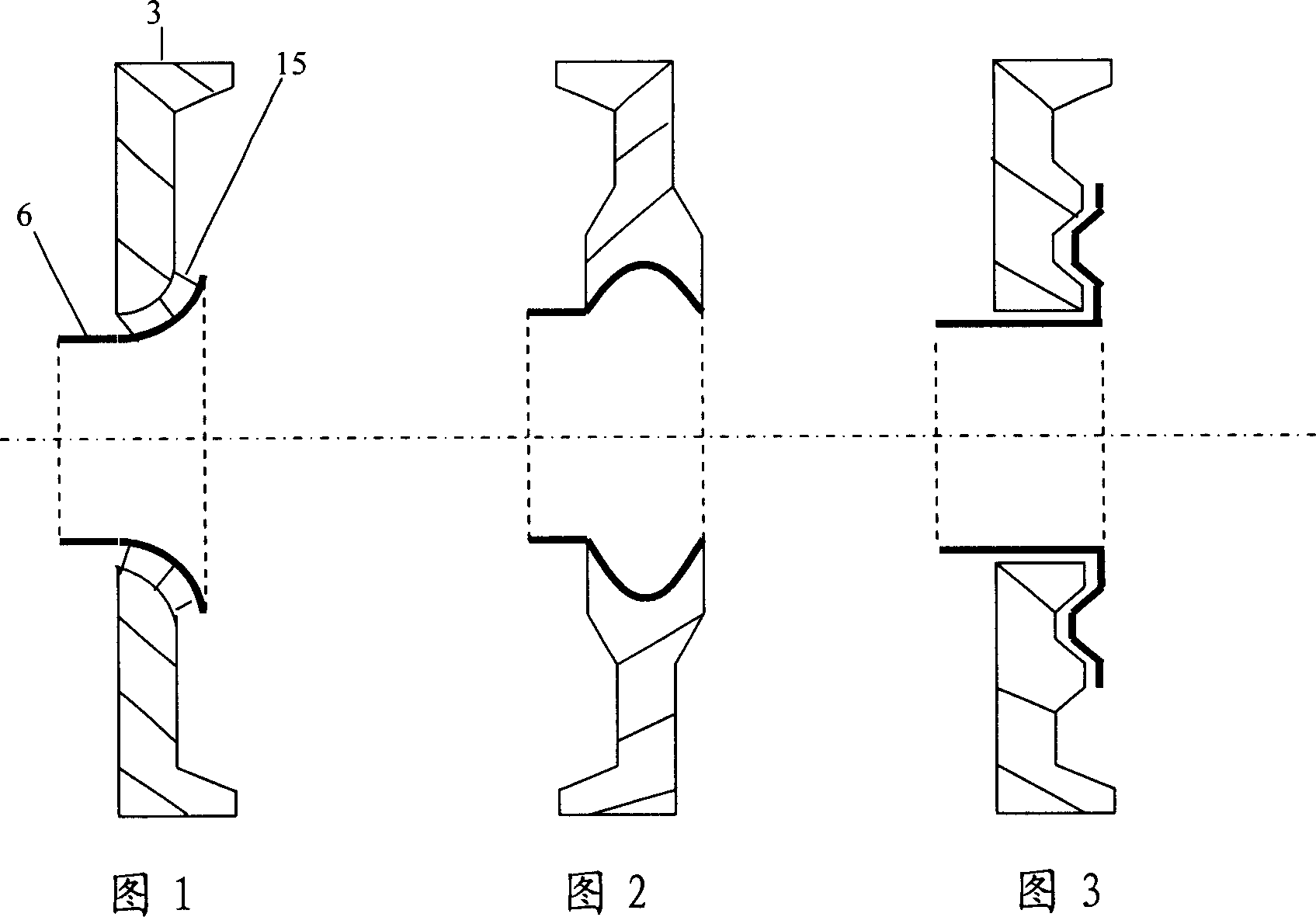
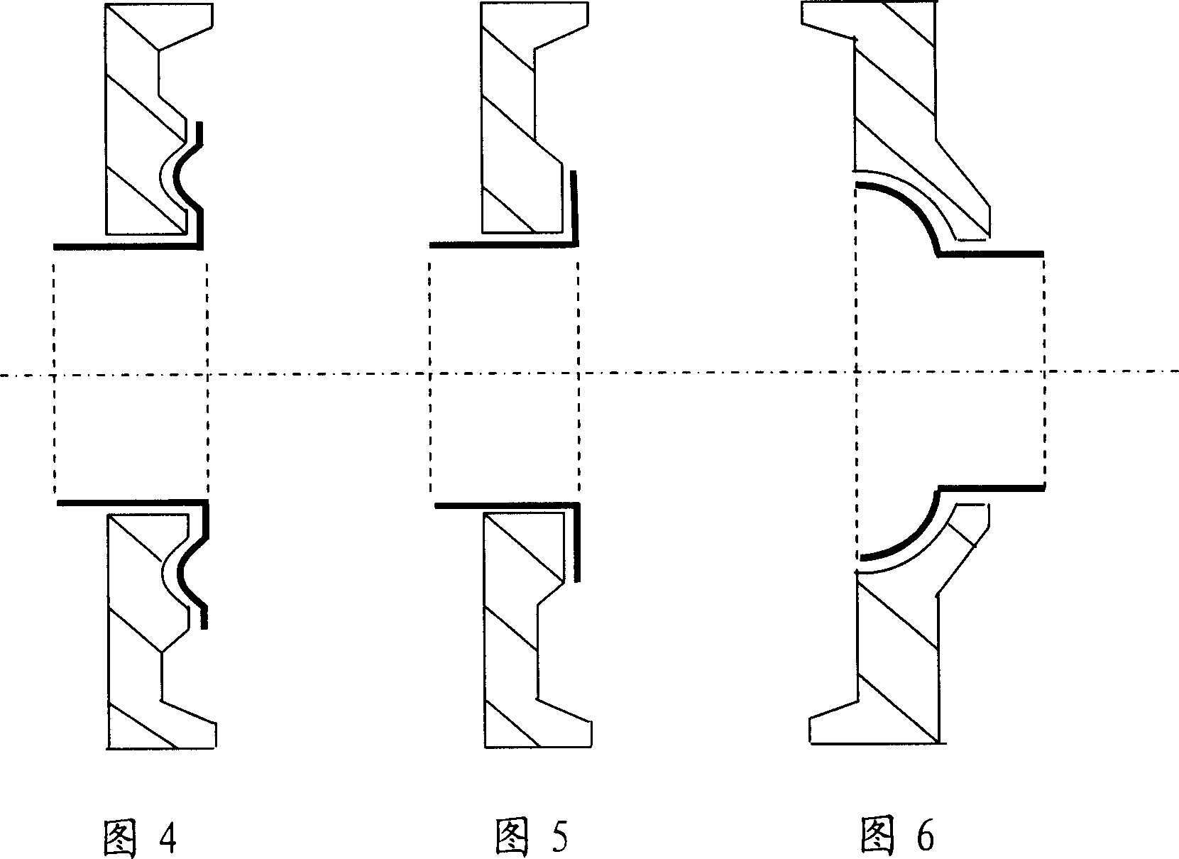
[0033] The new glass end cap 3 is made of the same material glass tube material, cut into sections, placed in the mold cavity for melting, and pressed by the mold to form a sealing surface end cap with a hemispherical tubular center and a flared tubular shape with outward flanging, or It is calcined from ceramic and glass-ceramic materials. The outer circle of the glass end cap 3 can be designed into various connection shapes, so that it can be welded with the glass outer tube 2 on the glass lathe, and the end caps made of ceramics and glass-ceramic materials can be welded indirectly. The iron-nickel Kovar alloy piece 6 is prefabricated into a corresponding hemispherical tubular shape and a trumpet tubular shape, and placed in the center of the glass end cover 3. Before placing, the glass sealing material 15 is placed between the two, and is selected in a high-temperature furnace. Welding iron-nickel Kovar alloy parts 6 at a temperature suitable for melting glass transition ma...

Embodiment 3

[0035] The new glass end cap 3 is formed by pressing a glass tube of the same material after melting in a mold cavity, or by calcining ceramics or glass-ceramic materials. Flat or grooved and corrugated sealing surfaces are pressed in the center. The iron-nickel Kovar alloy piece 6 is made into a T-shaped tube, and the top of the T-shaped top is prefabricated with a corresponding flat or grooved or corrugated connection surface, and placed in the center of the matching glass end cover 3 for welding; The T-shaped planar structure can also use the patent of pure aluminum pressure sealing. Other processes are the same as above. As shown in Figure 3, Figure 4, and Figure 5.


PUM

PropertyMeasurementUnit
Linear expansion coefficientaaaaaaaaaa
Softening temperatureaaaaaaaaaa

Abstract

The invention relates to medium-high-temperature solar vacuum heat collecting tube glass end cap packing structure and manufacture technique. The invention primarily solves the problem that the high external heat loss and complicate packing technique of the sealing terminal of the high temperature metal flow passage solar vacuum heat collecting tube under high pressure and high temperature condition, to provide new technical method to produce solar medium-high-temperature heat collecting tube. The glass end cap packing structure is composed by glass caps with different structure and relative nickel iron alloy strike component. The glass end cap component produced by The invention is useful to improving the mechanical connecting intensity of the glass metal solar vacuum heat collecting tube, to reduce the heat loss caused by heat radiating, heat convection, and heat conducting, to improve the stability of the vacuum heat collecting, it is useful to realizing specialized production.

Description

technical field [0001] The invention relates to a glass end cover packaging structure and manufacturing process for medium and high temperature solar vacuum heat collecting tubes. Vacuum tubes are used. It belongs to the technical field of solar thermal utilization. Background technique [0002] With the vigorous development of the use of renewable energy such as solar energy in the world, solar thermal power generation, solar refrigeration air conditioning, solar desalination and other solar energy industrial heat utilization technologies are gradually recognized by people, and the establishment of these solar heat utilization devices is inseparable from the trough (Parabolic) line focusing and compound paraboloid are CPC concentrating devices, and line focusing solar collector tube is the main heat collecting element in the system. However, due to the constraints of the packaging structure and technology, the current solar vacuum heat collector tubes with built-in metal ...

Claims


Application Information

Patent Timeline
IPC IPC(8): F24J2/46
CPCF24J2/055Y02E10/44F24S10/45
Inventor 张建城
Owner 中金盛唐新能源科技(北京)有限公司
Why Eureka
Try Eureka