Complex electrode structure of longitudinal stream gas discharge system

A technology of gas discharge and longitudinal flow, which is applied in the direction of circuits, electrical components, laser components, etc., can solve problems such as DC discharge discharge mode and electrode structure, and achieve the effect of increasing injection power, increasing concentration, and increasing output

Inactive Publication Date: 2007-10-31
DALIAN INST OF CHEM PHYSICS CHINESE ACAD OF SCI
View PDF0 Cites 4 Cited by
  • Summary
  • Abstract
  • Description
  • Claims
  • Application Information

AI Technical Summary

Problems solved by technology

Therefore, in order to improve F/DCl/HI/HN 3 The small signal gain and output power of the all-gas-phase iodine laser system must increase the yield of F atoms, because the number of fluorine atoms directly affec

Method used


Image

  • Complex electrode structure of longitudinal stream gas discharge system
  • Complex electrode structure of longitudinal stream gas discharge system
  • Complex electrode structure of longitudinal stream gas discharge system

Examples


Embodiment 1

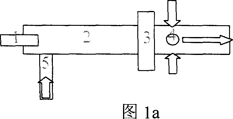
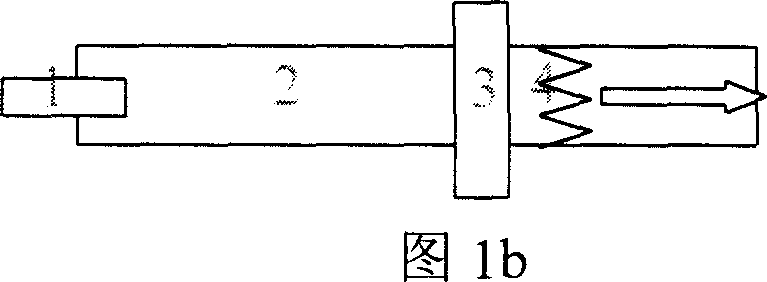
[0021] Please refer to Fig. 1, the inventive device consists of an anode, a quartz discharge tube, and a double cathode structure. The anode 1 is a cylindrical cavity structure, cooled by circulating water inside, connected to the quartz tube 2 through a plexiglass sealing sleeve, the first cathode 3 is an annular cavity structure, and internally circulated for cooling, and is also connected to the quartz tube 2 through a plexiglass sealing sleeve. Connected, the second cathode 4 is a spiral coil structure, placed vertically in the downstream transition section of the air flow, and internally circulated for cooling. 5 is an air inlet for flowing gas. The gas flows through the discharge tube, flows out from the center of the cathode 3 ring, and collides with the cathode 4 to increase disturbance and strengthen mixing.

[0022] The above electrode structure can be applied to the stable discharge of flowing gas, increasing the concentration of active particles and improving the u...

Embodiment 2

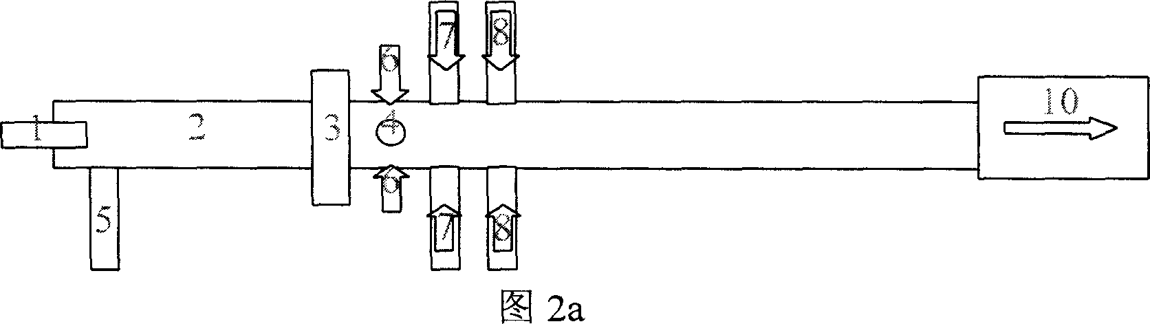
[0024] The following uses the application of the F / DCl / HI / HN3 all-gas-phase iodine laser system as an example to illustrate the method of using the electrode structure of the present invention.

[0025] The applicant used the electrode structure of the mixed reaction gas discharge system to generate active particle fluorine atoms, and applied the invention to the F / DCl / HI / HN3 all-gas-phase iodine laser system for the first time, and studied the discharge characteristics and injection power of the gas Condition.

[0026] Please refer to Figure 2. Since the F / DCl / HI / HN3 all-gas-phase iodine laser system is a mixed reaction of four gas streams to generate excited iodine atoms, it is possible to perform gain measurement and light demonstration. In this embodiment, the electrode structure of the mixed reactive gas flow discharge system of the present invention is used to perform DC discharge on the mixed gas of NF3 / He to generate active particle fluorine atoms, and the main gas flo...


PUM


Abstract

The invention is an electrode structure of flow gas discharging; concretely it is a compound electrode structure of lengthways flow gas discharging system that includes anode, quartz tube, double cathode, the anode is column cavity structure, it is connected with the quartz tube via airproof packet, two double cathodes are placed separately, the first cathode is ring cavity structure and it is connected with the quartz tube via airproof packet, the anode and the quartz tube, the quartz tube and the first cathode forms airproof structure, the second cathode is screw coil pipe structure, it is placed on transition section of air flow backward position outside the first cathode. The invention adopts double cathode structure to obtain perfect discharging stability; the infusing power is improved greatly; for chemical laser induced by discharging which is based on active particle, the production of active particle is increased greatly, the double cathode structure increases the utilizing efficiency of the active particle.

Description

technical field [0001] The invention relates to an electrode structure for flowing gas discharge, which improves the stability of gas flow discharge and strengthens the mixing between gas flows. The gas flow through this electrode structure not only increases the concentration of active particles, improves the stability of discharge, but also improves the utilization efficiency of active particles, thereby promoting the development of flowing gas discharge. Background technique [0002] The development of oxygen iodine chemical laser has a history of 20 years, and it also has a certain scale. Because the oxygen generator is a gas-liquid reaction, it is difficult to increase the volume specific power of the oxygen-iodine chemical laser. Therefore, reducing the volume and weight of the oxygen-iodine laser is limited. In 1990, Bower and Yang reported that NCl(a 1 The energy transfer of Δ)+I has attracted great attention from people all over the world. By NCl(a 1 Δ) Whether ...

Claims


Application Information

Patent Timeline
IPC IPC(8): H01S3/038
Inventor 多丽萍金玉奇桑凤亭唐书凯于海军汪健
Owner DALIAN INST OF CHEM PHYSICS CHINESE ACAD OF SCI
Why Eureka
Try Eureka