Mask loading technology

A mask plate and process technology, applied in the field of photolithography, can solve the problems of reducing loading efficiency, failure to reduce errors, difficulties, etc., and achieve the effects of reducing computational complexity, improving loading accuracy, and reducing the number of repetitions

Active Publication Date: 2007-11-07
SHANGHAI MICRO ELECTRONICS EQUIP (GRP) CO LTD
View PDF0 Cites 22 Cited by
  • Summary
  • Abstract
  • Description
  • Claims
  • Application Information

AI Technical Summary

Problems solved by technology

[0011] 1. The "fine pre-alignment" process cannot reduce the errors introduced by the "reticle handover" process
[0012] In the above-mentioned reticle loading process, the "reticle transfer" process is located after the "fine pre-alignment" process. In the "reticle transfer" process, due to factors such as assembly errors and vibrations between systems, new errors will be generated. And the process accuracy of "reticle handover" is often lower than that of "fine pre-alignment", which makes the error of loading process larger
[0013] 2. It is difficult to accurately calibrate the coordinate relationship between the mask plate transmission system and the mask table system
However, the mask transfer system and the mask stage system are independent of each other and exist in two coordinate worlds o 3 ’, o 1 ’, it is very difficult to accurately calibrate the coordinate relationship between the two systems, and there is a lack of effective measurement means and methods
If the coordinate relationship between the two systems is not calibrated accurately, the accuracy of the "fine pre-alignment" link will often fail to meet the requirements, or multiple pre-alignment actions will be required to meet the accuracy requirements, greatly reducing the loading efficiency

Method used


Image

  • Mask loading technology
  • Mask loading technology
  • Mask loading technology

Examples


Embodiment Construction

[0028] The reticle loading process of the present invention will be further described in detail below with reference to the accompanying drawings.

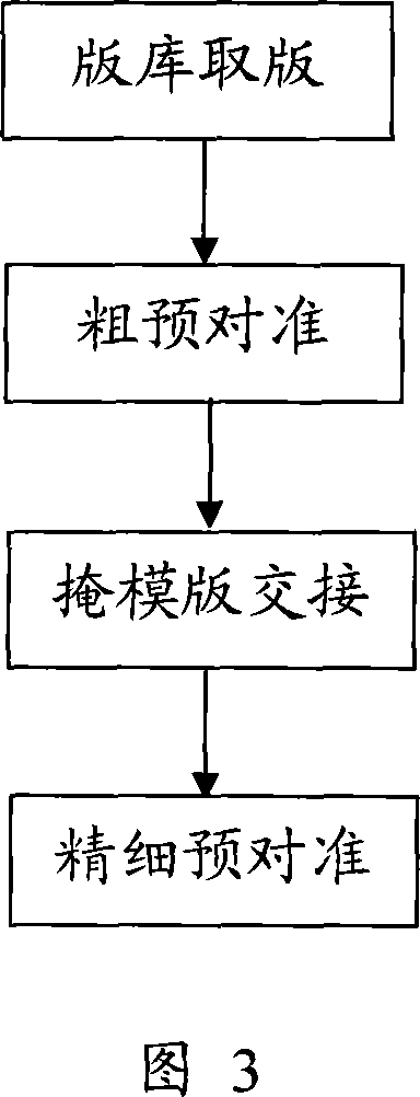
[0029] As shown in FIG. 3 , the reticle loading process of the present invention includes four processes: receptacle retrieval, rough pre-alignment, reticle transfer, and fine pre-alignment. Among them, the process of plate picking and rough pre-alignment from the plate library is completed on the mask transmission system, the reticle handover process is completed by the cooperation of the mask transmission system and the mask table system, and the fine pre-alignment process is completed on the mask table system.

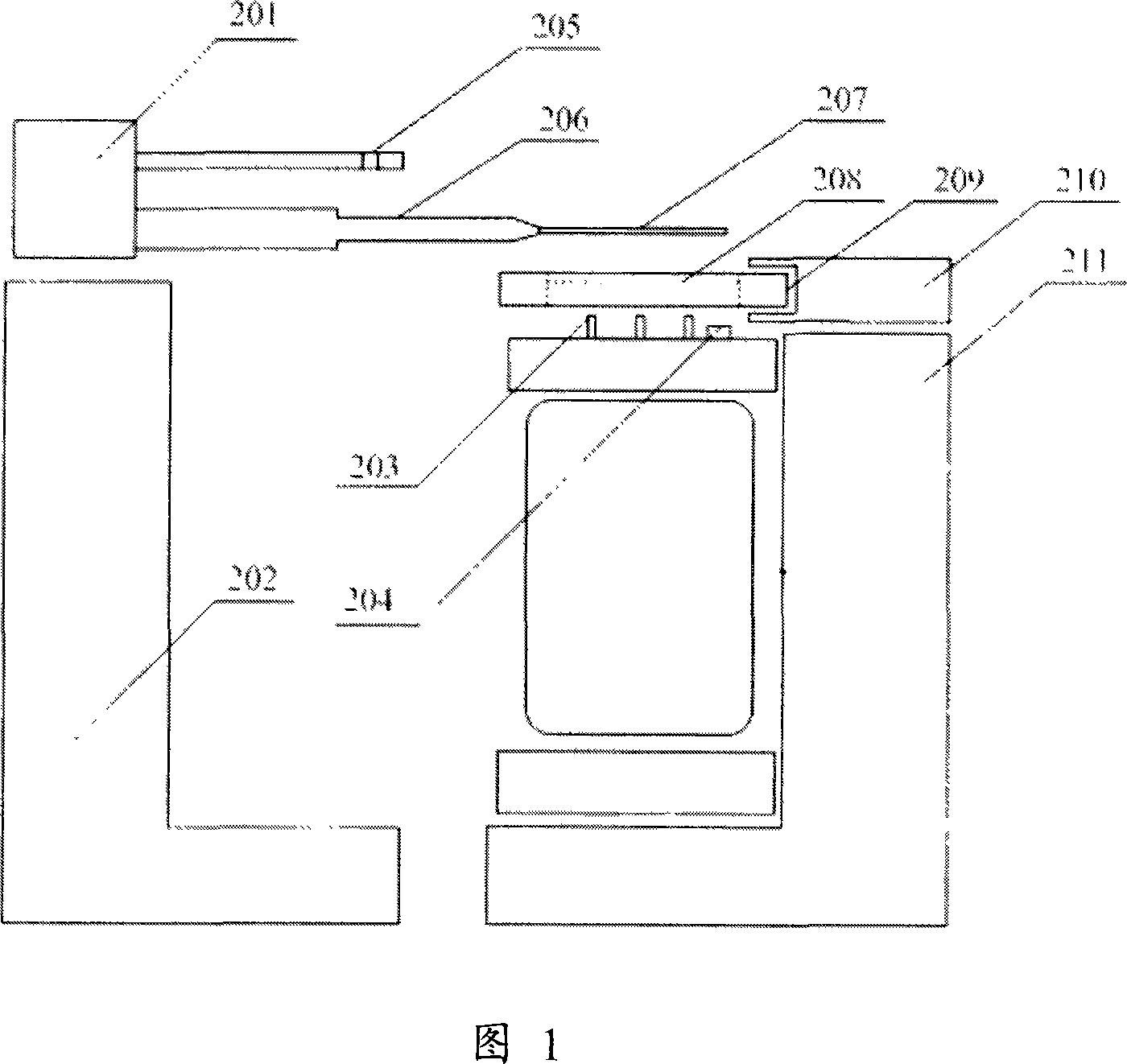
[0030] With reference to FIG. 1 , when performing the reticle loading process, the mask transfer system 202 firstly performs reticle picking and rough pre-alignment to achieve a certain reticle loading accuracy, and then cooperates with the mask stage system 211 to realize the reticle loading process. The stencil is han...


PUM


Abstract

The invention discloses a mask plate loading technology. It includes the following steps: taking plate from the bank; rough pre-aiming; mask plate connecting; fine pre-aiming. The precision of invention can reach that x direction minus or plus 1um, y direction minus or plus 1um, rz direction minus or plus 0.05mrad. Meanwhile, the fine pre-aiming can be reduced from traditional 3-5 times to 1 time, which can greatly increase pre-aiming efficiency and production rate.

Description

technical field [0001] The invention belongs to the field of photolithography, in particular to a mask plate loading process of a photolithography machine. Background technique [0002] In the lithography machine equipment, the alignment system has a limited capture range for the reticle mark, generally around 10 μm, and the maximum does not exceed 40 μm, which requires that the error of the reticle loaded to the carrier be controlled within a certain error range , otherwise the alignment system will fail because it cannot find the marker. [0003] Existing lithography machines have introduced a pre-alignment link in the mask plate loading process, such as the 6300 and 8000 lithography machines of GCA Corporation in the United States, which control errors through mechanical pre-alignment. Another example is the 2000 and 5000 lithography machines of ASML in the Netherlands, which control the loading error of the reticle through optical pre-alignment. In some lithography mac...

Claims


Application Information

Patent Timeline
Patent Type & Authority Applications(China)
IPC IPC(8): G03F7/20H01L21/027
Inventor 沈锦华张方元杨锋力
Owner SHANGHAI MICRO ELECTRONICS EQUIP (GRP) CO LTD
Why Eureka
Try Eureka