

Electrostatic spray apparatus
A technology of electrostatic spraying and nozzles, applied in the field of electrostatic spraying devices, which can solve problems such as difficulty in ensuring the reliability of electrostatic spraying devices, increased manufacturing costs, and complicated structures of electrostatic spraying devices
- Summary
- Abstract
- Description
- Claims
- Application Information
AI Technical Summary
Problems solved by technology
Method used
Image

Examples
no. 1 example
A first embodiment of the present invention will be described.
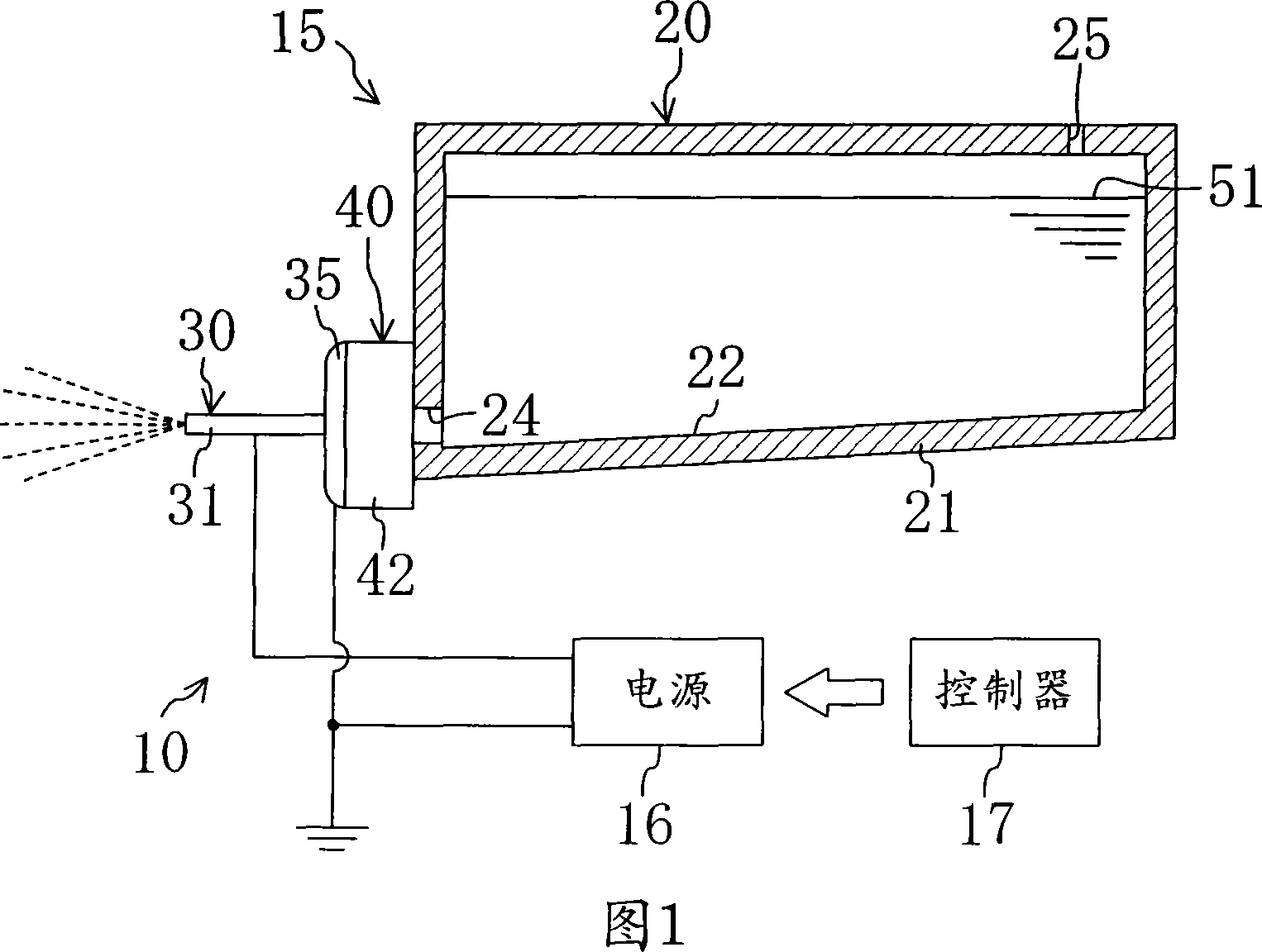
[0071] As shown in Figure 1, the electrostatic spraying device (10) of this embodiment includes a spray box (15), a power supply (16) and a controller (17).
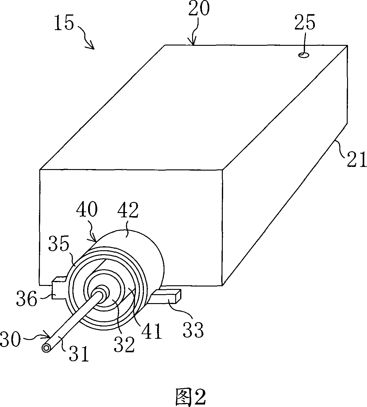
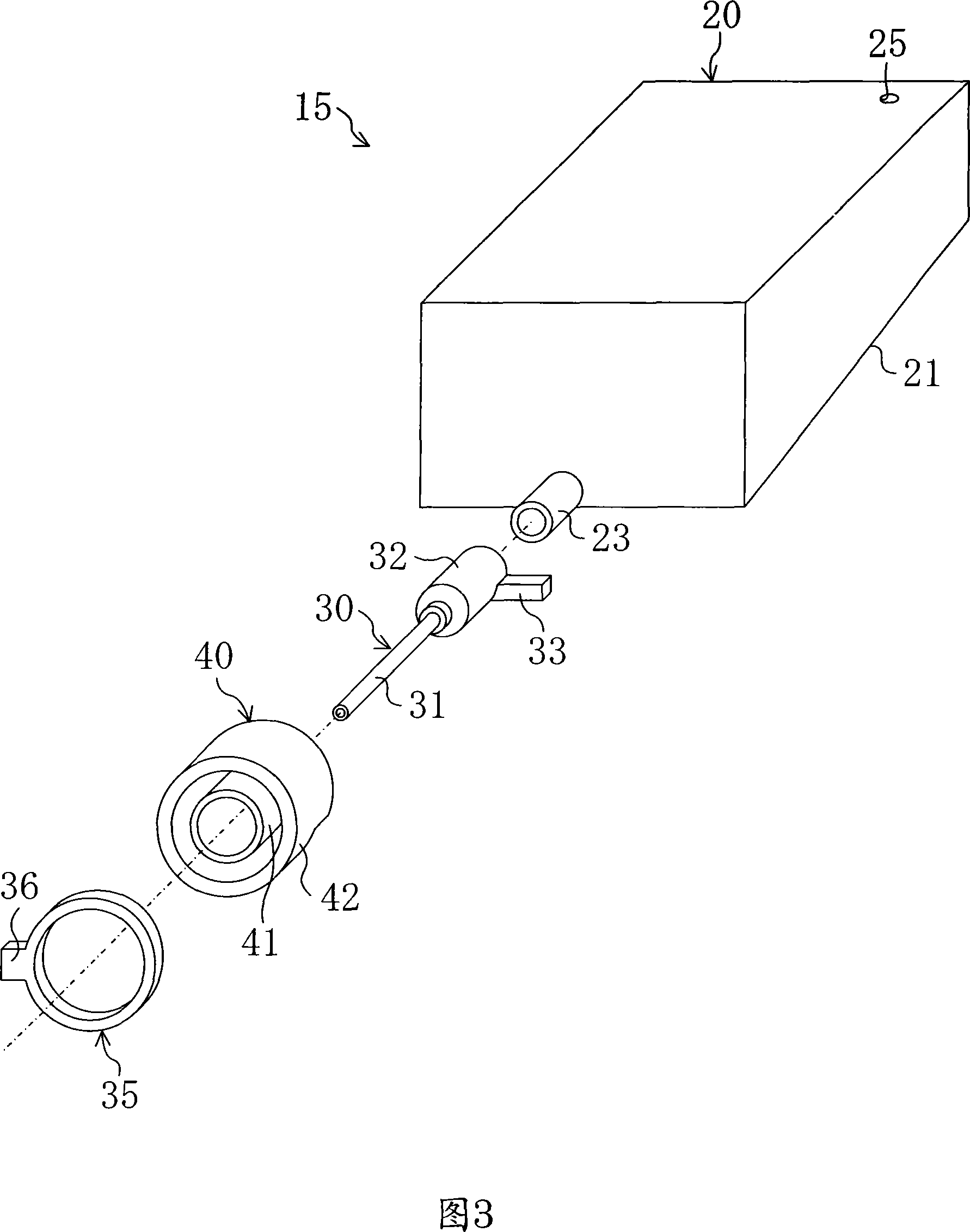
[0072] As shown in Figures 2 and 3, the spray box (15) includes: a solution box (20), a nozzle unit (30), an electrode holder (40) and a ring electrode (35).
[0073] The solution tank (20) constitutes a container part, including a tank main body (21). The box main body (21) is a hollow container formed in a slightly flattened cuboid shape. On the top plate of the box main body (21), vent holes (25) are formed. The bottom surface (22) of box main body (21) is from the back side of box main body (21) (the side surface of the farthest side among Fig. 1, Fig. 2 and Fig. 3) to box main body (21). The front surface (the left side surface in FIG. 1, the side surface on the nearest side in FIGS. 2 and 3) of the front surface is inclined. In the box main body (2...
no. 3 example
A third embodiment of the present invention will be described. In this embodiment, the shape of the spray nozzle (31) is changed in the spray box (15) of the first embodiment. It should be added that the spray nozzle (31) of this embodiment can also be used in the spray box (15) of the second embodiment.
[0128] The inner diameter of the spray nozzle (31) of this embodiment is constant at all positions along the length of the spray nozzle (31). On the other hand, the vicinity of the tip of the spray nozzle (31) has a tapered shape in which the outer diameter of the spray nozzle (31) gradually decreases as it approaches the tip of the spray nozzle (31). In the spray nozzle (31), the portion formed in a tapered shape constitutes a front end portion (31a). The tip of the tip portion (31a) of the spray nozzle (31) is shaped like a knife edge, and the thickness of the tip is basically 0 mm.
[0129] Referring to Fig. 18, the detailed shape of the spray nozzle (31) will be descri...
no. 4 example
[0140] As shown in FIG. 25 and FIG. 26, the front end surface (31b) of the spray nozzle (31) of this embodiment has been processed to form a narrow groove (19) as a hydrophilization treatment. Specifically, a groove (19) extending in a radial direction is formed in a front end surface (31b) of the spray nozzle (31). Eight grooves (19) are formed at equal intervals. The width of the groove (19) is extremely small compared to the length of the inner circumference or the length of the outer circumference. Therefore, when the conical gas-liquid interface (52) was formed at the front end of the spray nozzle (31) during the spray process, due to capillary phenomenon, the liquid was provided in the entire groove (19), and the entire front end surface of the spray nozzle (31) ( 31b) It is easy to become a wet state.
[0141] As an additional note, it may also be such that in the spray nozzle (31) of the first modification (see FIG. 21 ) or the third modification (see FIG. 23 ) of th...
PUM
| Property | Measurement | Unit |
|---|---|---|
| The inside diameter of | aaaaa | aaaaa |
Abstract
Description
Claims
Application Information