Combined fork-type blade-root milling cutter

A combined and fork-shaped technology, which is applied in the direction of milling cutters, milling machine equipment, manufacturing tools, etc., can solve the problems of less indexing times, scrapped cutter bodies, and short tool life, so as to increase indexing times and prolong service life , The effect of high positioning accuracy

Inactive Publication Date: 2007-11-14
DONGFANG TURBINE CO LTD
View PDF0 Cites 6 Cited by
  • Summary
  • Abstract
  • Description
  • Claims
  • Application Information

AI Technical Summary

Problems solved by technology

In reality, the machining tool for this kind of slots mostly adopts a combined fork-type blade root milling cutter. According to the number of blade root slots and the characteristics of the shape line, a set of milling cutters combined with multiple milling cutters is generally designed to process the blade root slots. Since the outer edge of the combined fork-type blade root milling cutter currently used and the blades distributed on the circumference of the cutter body are positioned and fixed with the cutter body in a side-positioning manner, and the outer edge itself is small due to the small width of the processed groove, resulting in a The edge of the body and the blade is thinned, which greatly reduces the strength of the outer edge of the cutter itself. It is very easy to break during the cutting process, and even causes the cutter body to be scrapped as a whole; Structural reason is that the number of indexable positions is small, resulting in low utilization rate of blade materials and waste of materials; the above two situations have led to high cost of such tools in the industry, short tool life, affecting production efficiency and processing quality. A kind of defect, inventor has carried out improved design to this kind of cutting tool

Method used


Image

  • Combined fork-type blade-root milling cutter
  • Combined fork-type blade-root milling cutter
  • Combined fork-type blade-root milling cutter

Examples


Embodiment Construction

[0016] Below in conjunction with accompanying drawing, technical scheme of the present invention is described further:

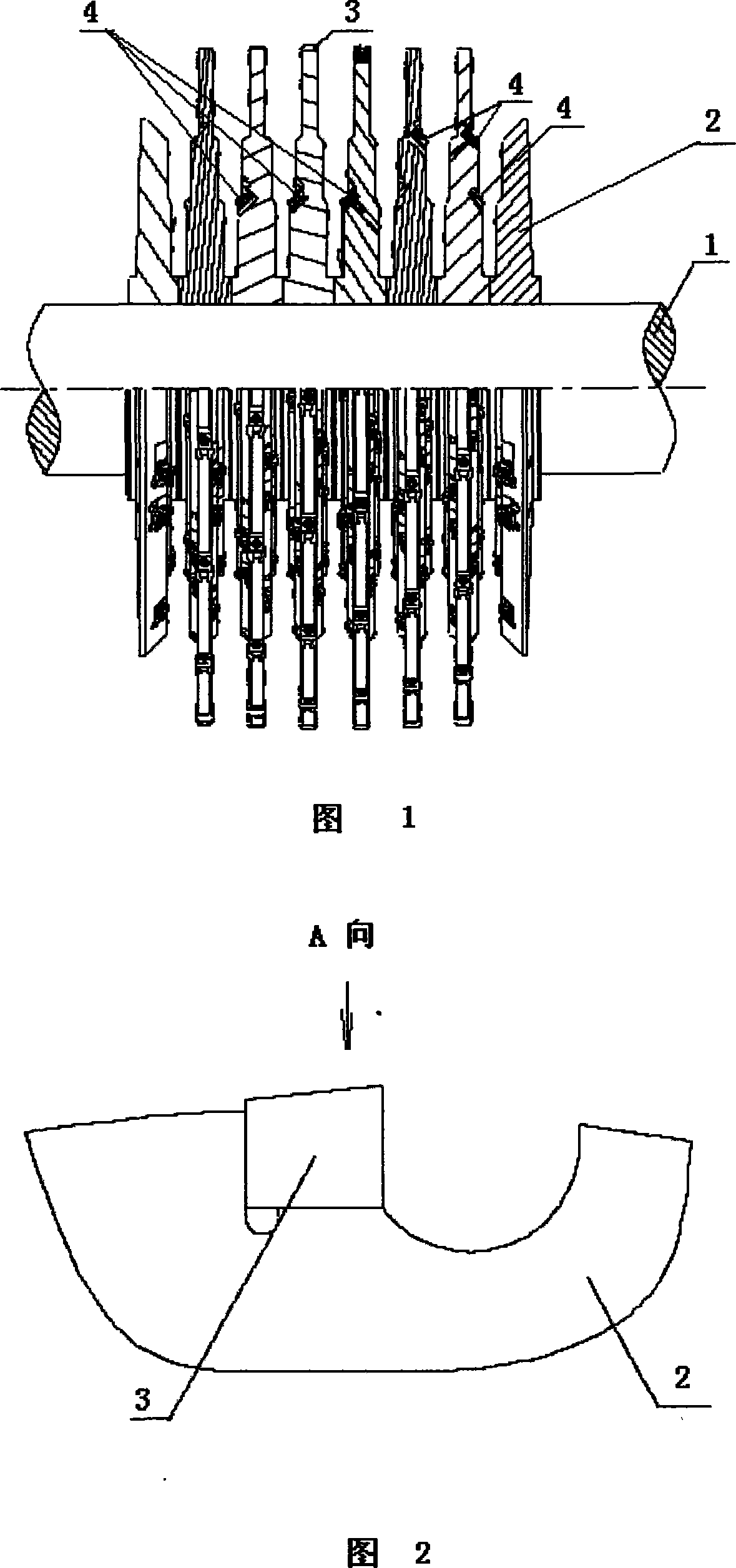
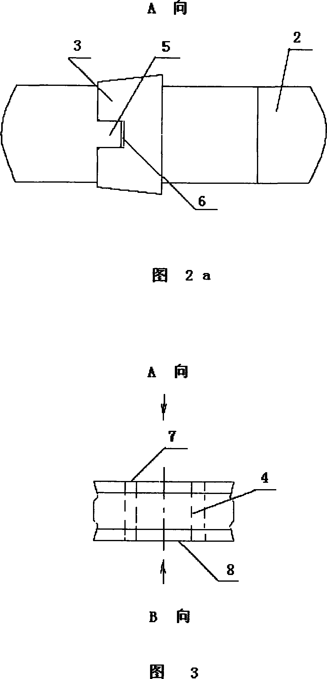
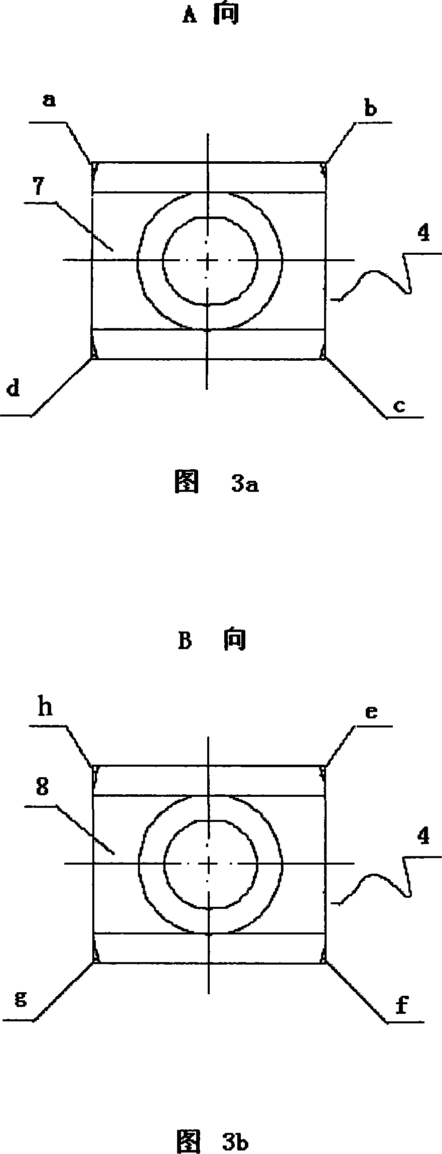
[0017] As shown in Figure 1, the combined fork-type blade root milling cutter of the present invention consists of a rotating shaft 1, a disc-shaped cutter body 2, blades 3 installed on the outer edge of the disc-shaped cutter body 2 and distributed along the circumference, and installed on both sides of the disc-shaped cutter body 2 The disk surface consists of 4 indexable inserts. On each disc-shaped cutter body 2, according to the difference in the number of blade fork-shaped blade root grooves, more than two disk-shaped cutter bodies 2 can be installed on the rotating shaft 1. According to the shape characteristics of the blade fork-shaped blade root grooves, each At least two indexable inserts 4 are installed in the circumferential direction at different diameters of the disc surfaces on both sides of a disc-shaped cutter body 2 . The disk-shaped cutte...


PUM


Abstract

The invention provides a combined fork-shape blade-root milling cutter. It has a shaft with at least two discoid cutter bodies. At least two blades are equipped along circumferential direction on the outer fringe of the discoid cutter bodies. On the two side disk surfaces of the discoid cutter bodies set at least two turnable blades respectively. The outer fringes of the cutter is connected with the blade by keys. The rotary blades have 5-8 cutting edges. The advantages of the milling cutter are: joint of the outer fringe of the discoid cutter bodies and the blades has high intensity. The cutter body has long service life. With 5-8 cutting edges, each rotary blade improves its service life. It changes blade quickly, has high precision and reliable positioning and can save materials.

Description

technical field [0001] The invention relates to a machining tool, in particular to a milling tool for a root slot of a fork blade of a steam turbine and a similar structural part. Background technique [0002] As we all know, high-speed steel cutting tools have been widely used in the field of mechanical processing due to their good toughness, sharp cutting edge and not easy to chip when used. Although in many respects, cemented carbide is superior to high-speed steel, but under some specific processing conditions, cemented carbide cannot completely replace high-speed steel due to insufficient toughness and unsharpness. However, as the price of high-speed steel raw materials continues to rise, the overall cost of high-speed steel tools has increased rapidly. How to reduce the manufacturing cost of high-speed steel tools has become a problem that tool manufacturers must consider. [0003] The machining of root slots of long blades of steam turbines has always been a major di...

Claims


Application Information

Patent Timeline
Patent Type & Authority Applications(China)
IPC IPC(8): B23C5/20B23C5/08
Inventor 吴波刘文泽李启山李勇孙长荣徐志明周良才胡剑华
Owner DONGFANG TURBINE CO LTD
Why Eureka
Try Eureka