Methods and apparatuses for connecting receive coils in magnetic resonance imaging scanners

A technology for magnetic resonance imaging and magnetic resonance signals, which is applied in magnetic resonance measurement, measurement devices, instruments, etc., can solve problems such as increasing the complexity of coil components, and achieve the effect of reducing the number of

Inactive Publication Date: 2007-11-14
KONINKLIJKE PHILIPS ELECTRONICS NV
View PDF1 Cites 14 Cited by
  • Summary
  • Abstract
  • Description
  • Claims
  • Application Information

AI Technical Summary

Problems solved by technology

Feld et al. disclose the use of dynamic signal compression circuitry on the coil, however, this increases the complexity of the coil assembly and may introduce signal distortion into the compressed signal

Method used


Image

  • Methods and apparatuses for connecting receive coils in magnetic resonance imaging scanners
  • Methods and apparatuses for connecting receive coils in magnetic resonance imaging scanners
  • Methods and apparatuses for connecting receive coils in magnetic resonance imaging scanners

Examples


Embodiment Construction

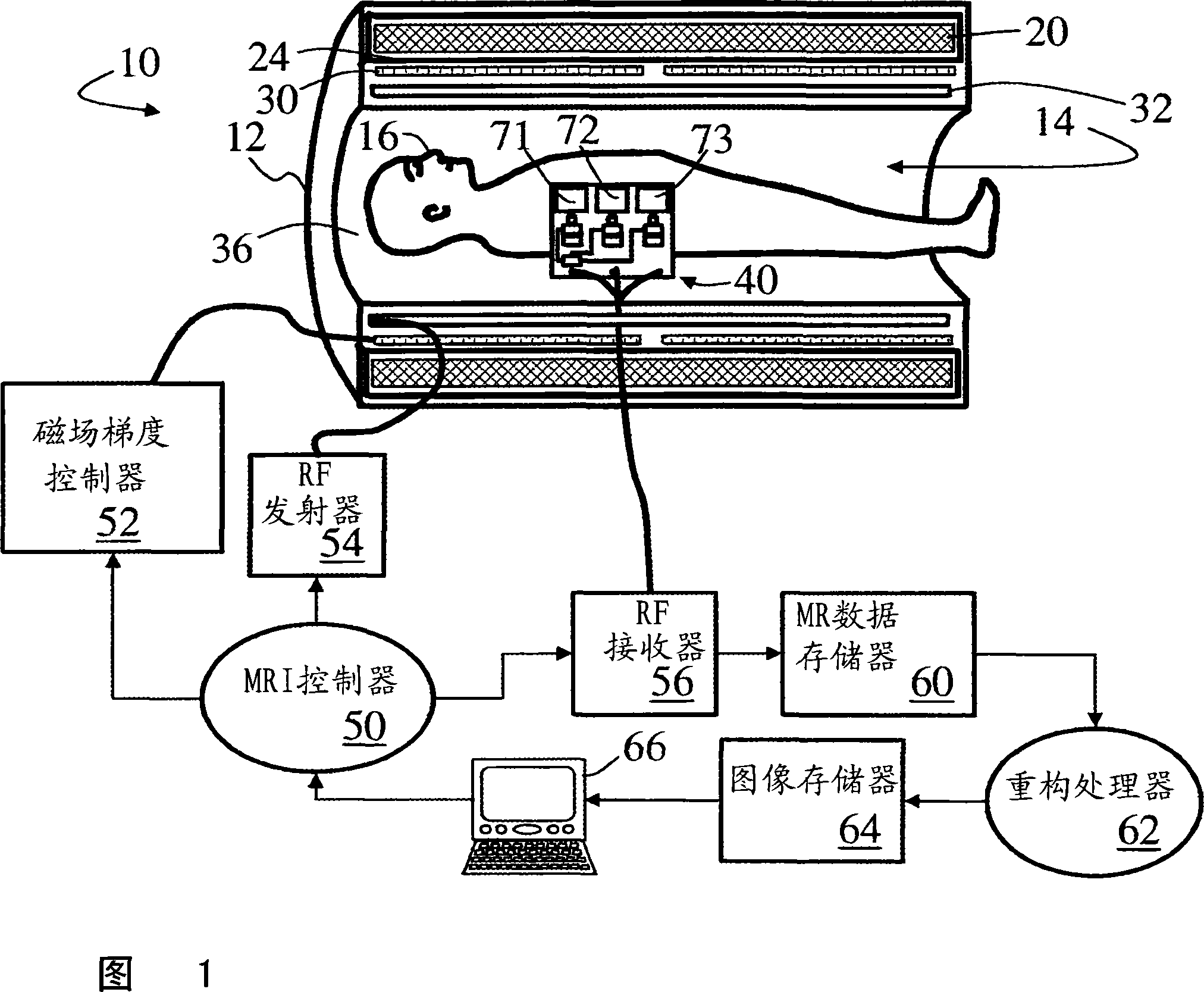
[0020] Referring to FIG. 1 , a magnetic resonance imaging scanner 10 includes a housing 12 that defines an examination region 14 in which a patient or other imaging subject 16 is placed. A main magnet 20 arranged in the housing 12 generates a main magnetic field in the examination region 14 . Typically, the main magnet 20 is a superconducting magnet surrounded by a cryoshrouding 24; however, resistive main magnets may also be used. Magnetic field gradient coils 30 are arranged in or on this housing 12 to superimpose selected magnetic field gradients on the main magnetic field in the examination region. An apparatus for injecting radio frequency excitation pulses into an examination region is provided. In the depicted embodiment, an integral radio frequency coil 32, such as a birdcage coil, is disposed in or on the housing 12 to inject radio frequency excitation pulses into the examination region. In other embodiments, a head coil, arm or leg coil, surface coil, or other type...


PUM


Abstract

A coils array (40, 40') including a plurality of coils (71, 72, 73) receives magnetic resonance signals from an examination region of a magnetic resonance imaging scanner (10). Each coil has mixing circuitry (74, 75, 76, 80, 81, 82) that frequency-shifts the received magnetic resonance signal to a selected transmission channel frequency. The coils array further includes combining circuitry (90) that combines the frequency-shifted magnetic resonance signals to produce an analog frequency domain multiplexed transmission signal output of the coils array. Receiver electronics (56, 56'') receive the analog frequency domain multiplexed transmission signal from the coils array. The receiver electronics include an analog-to-digital converter (164) that digitizes the analog frequency domain multiplexed transmission signal and digital signal processing circuitry (166) that processes the digital frequency domain multiplexed transmission signal to recover digitized signals corresponding to the magnetic resonance signals received by the plurality of coils.

Description

technical field [0001] This application relates to the field of magnetic resonance. The present application finds particular application in magnetic resonance imaging using multiple receive coils and will be described herein with particular reference thereto. More generally, the present application finds application in magnetic resonance spectroscopy, imaging, and the like. Background technique [0002] Magnetic resonance imaging increasingly employs multiple receive coils during imaging to provide increased data acquisition speeds, larger fields of view, and other advantages. Many techniques, such as parallel imaging, sensitivity encoding (SENSE), etc., use multiple coils, eg 4 coils, 8 coils, etc. Large coil arrays with 32 or more coils are considered in some of these imaging techniques. The receive coils are placed close to the imaging object. Each coil has an analog coaxial output conductor, and the coaxial output conductors of the multiple coils are bundled into one...

Claims


Application Information

Patent Timeline
Patent Type & Authority Applications(China)
IPC IPC(8): G01R33/3415G01R33/36
CPCG01R33/3621G01R33/3415G01R33/3692
Inventor G·埃恩霍姆
Owner KONINKLIJKE PHILIPS ELECTRONICS NV
Why Eureka
Try Eureka