Manufacture of bridging crane main beam

An overhead crane and manufacturing process technology, applied in the directions of load hanging elements, transportation and packaging, support structures, etc., can solve the problems of lower deflection of the main beam of the crane, lowering of the lifting weight, and gnawing of rails by carts, so as to increase the cutting capacity. The effect of area, low cost and convenient construction

Inactive Publication Date: 2007-11-21
傅萍 +1
View PDF1 Cites 7 Cited by
  • Summary
  • Abstract
  • Description
  • Claims
  • Application Information

AI Technical Summary

Problems solved by technology

At the same time, the elastic deflection of the main girder is specified F ≤ L k 700 (calculated fr...

Method used


Image

  • Manufacture of bridging crane main beam
  • Manufacture of bridging crane main beam
  • Manufacture of bridging crane main beam

Examples


Embodiment Construction

[0010] The implementation of the present invention will be described in detail below in conjunction with the accompanying drawings.

[0011] The first step: preparation process:

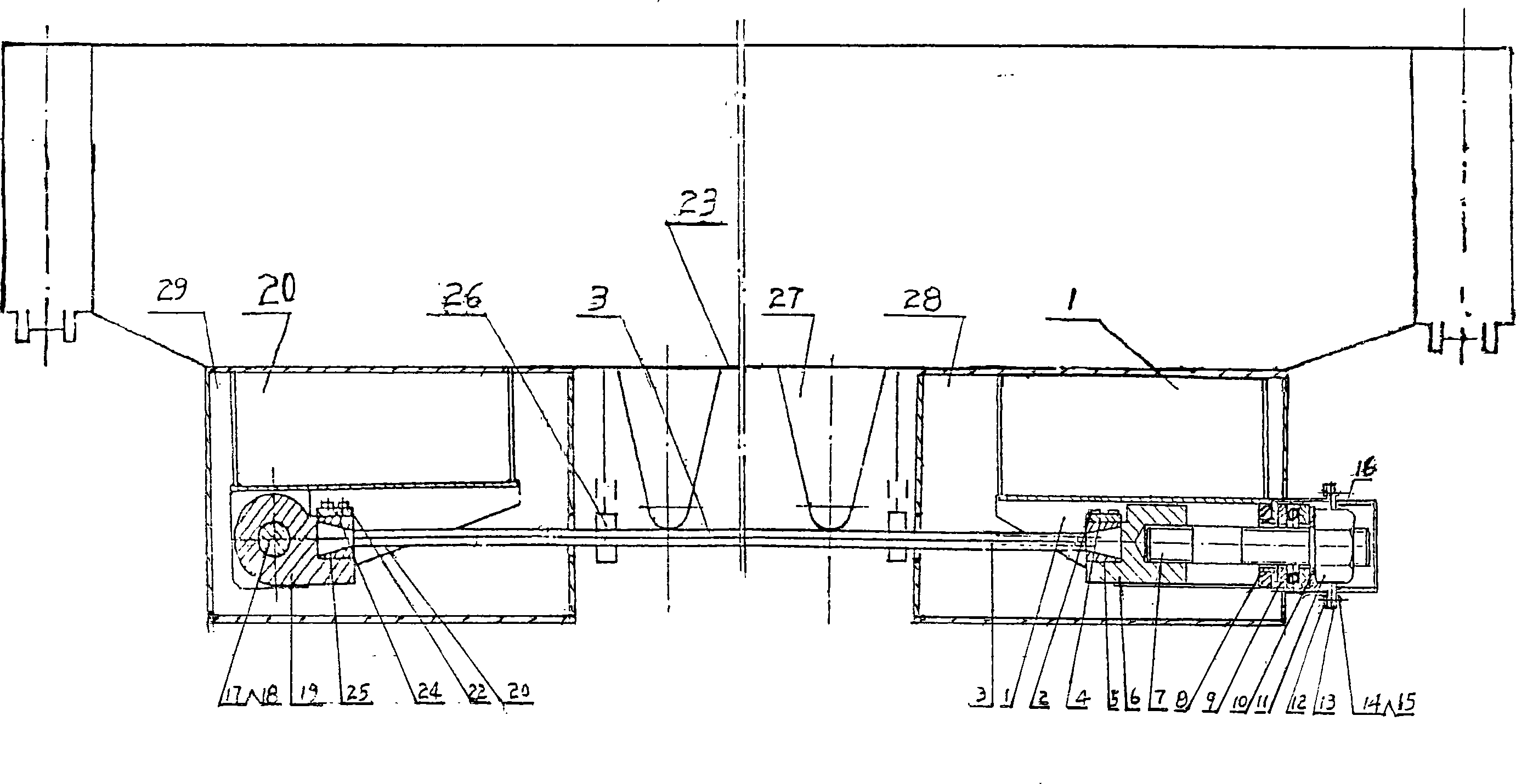
[0012] Lift the crane main girder that has been completed according to the main beam manufacturing drawings and processes of the bridge crane, and position the lower cover plate at a height of 1.4-1.6 meters from the ground. Support the main girder and end girder with a supporting frame or pads to make them fall stably.

[0013] The second step: welding process:

[0014] Place the tensioner box 1 in the additional rectangular parallelepiped tensioner transition box 28, weld it into a whole piece, set some reinforcement plates as required, and then weld the whole piece to one end of the lower cover plate of the main beam 23, Rope head is connected hinge support 20 and is placed in the cuboid connection hinge support transition box 29 of setting up again, is welded into whole, and is welded on the ot...


PUM


Abstract

The invention is concerned with the produce technology of bridge type of crane main girder. Seal the box of tensegrity ware and the added transition box of tensegrity ware into a whole and seal at one end of cover board under the main girder, and seal the branch seat of rope connecting ream and the added transition box to branch seat of connecting ream into a whole and seal at the other end of cover board under the main girder. Mould the end of rope into the cone-shaped lumen with Sn-based babbit alloy. This technology is fit for producing the bridge type of crane main girder when the loading-capacity is less than 100 tons. The main girder is always in the range of national technology standard and increases the shear surface to enhance the intensity, static rigidity and loading-capacity. It saves steels and reduces the cost about 20 percent and extends the work time at the same time.

Description

technical field [0001] The invention relates to a crane manufacturing process, in particular to a bridge crane main girder manufacturing process. Background technique [0002] Bridge crane is a special equipment widely used by industrial and transportation material enterprises. In order to ensure the performance requirements of the crane and avoid the phenomenon of "climbing" and "sliding" of the electric trolley as far as possible, the main girder of the crane must have a certain degree of camber. my country The crane manufacturing technical standard stipulates the upper camber of the main girder span when the main girder of the crane is unloaded. f 0 = L k 1000 + 0.4 - 0.1 (L K is the span of the cran...

Claims


Application Information

Patent Timeline
IPC IPC(8): B66C6/00
Inventor 傅萍傅昆傅国华
Owner 傅萍
Why Eureka
Try Eureka