Clutch-separating cable

A technology of clutches and pulleys, applied in clutches, mechanically driven clutches, control devices, etc., can solve the problems of stiff operation of the clutch mechanism, laborious clutch operation, and large bearing force of the clutch pedal, so as to achieve small loss of mechanical efficiency, easy operation, and improved The effect of force transmission efficiency

Inactive Publication Date: 2007-11-21
力帆科技(集团)股份有限公司
View PDF0 Cites 0 Cited by
  • Summary
  • Abstract
  • Description
  • Claims
  • Application Information

AI Technical Summary

Problems solved by technology

The structure of the mechanical clutch cable is simple and the price is cheap. The clutch cable is a steel wire rope. One end of the steel rope is connected to the pedal at the driver's place, and the other end is connected to the clutch release arm of the car. The position is accurate, the support is fixed on the car body, and the wire rope passes through the hole on the support. The structure of the whole mechanical clutch cable is simple and the price is cheap; but the mechanical clutch cable is mainly transmitted by a thin steel rope. , the power is transmitted in a 1:1 ratio, resulting in excessive load on the clutch pedal
[0003] The disadvantages of the current domestic clutch are: the clutch operation is laborious, the operation of the entire clutch mechanism is relatively blunt, and the clutch pedal bears too much force

Method used


Image

  • Clutch-separating cable
  • Clutch-separating cable
  • Clutch-separating cable

Examples


Embodiment 1

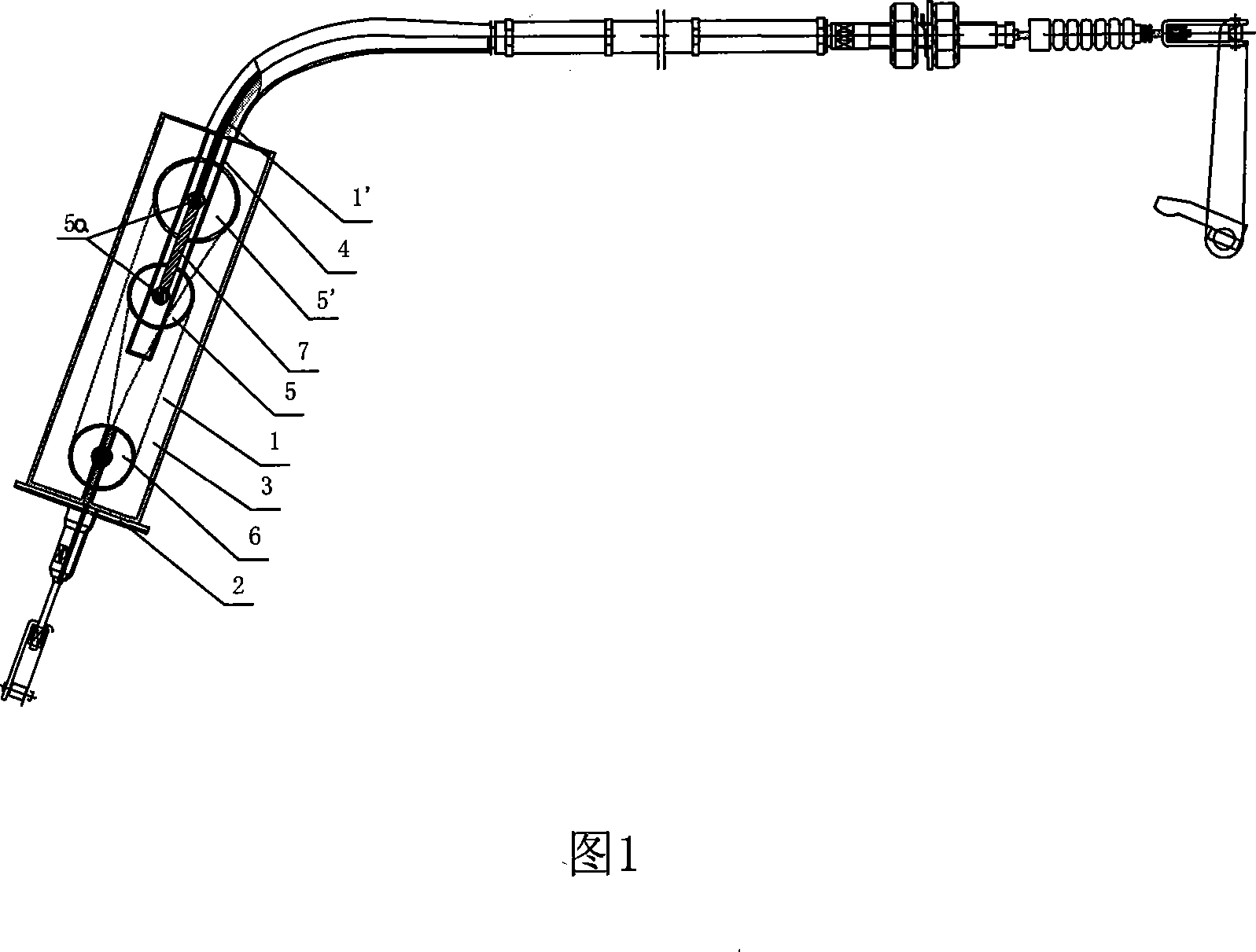
[0020] As shown in Figures 1 and 2: a clutch release cable device is composed of a pedal cable 1, a support 2, a pulley positioning box 3, a pulley mechanism, a pedal cable 1 and a release cable 1', the support 2 is fixed with a pulley positioning box 3, the pulley positioning box 3 is provided with a pulley mechanism, the pedal cable 1 passes through the support 2, stretches into the pulley positioning box 3 from one end of the pulley positioning box 3, and After bypassing the pulley mechanism, it is fixed on the pulley positioning box 3; a separation cable 1' is fixedly connected to the center of the pulley mechanism, and the separation cable 1' is connected from the other end of the pulley positioning box 3 Stretch out this pulley positioning box 3 outside.

[0021] Described pedal stay cable 1 and separation stay cable 1 ' are steel wire ropes.

[0022] The device is simple in structure, compact, small in size and cheap in price. It uses the traditional mechanical clutch ...

Embodiment 2

[0025] Embodiment 2, the structure principle of this embodiment 2 is consistent with that of embodiment 1, the difference is that

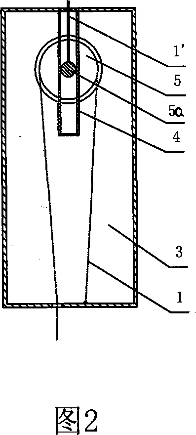
[0026] As shown in Fig. 1, 3: described pulley mechanism is made up of fixed pulley block, movable pulley groove 4, movable pulley block, wherein movable pulley groove 4 is fixed in the described pulley positioning box 3, and described movable pulley block is made up of at least two movable pulleys 5, The main shafts of the two movable pulleys 5 are vertically inserted into the movable pulley groove 4, and interlocking bars 7 are fixedly connected between the main shafts 5a of each movable pulley 5, and the separation cable 1' is fixed on the main shaft 5a; After cable 1 stretches into the pulley positioning box 3, it is fixed on the described pulley positioning box 3 after walking around the movable pulley block and the fixed pulley block.

[0027] The inner wall of the pulley positioning box 3 is provided with a wire-passing pipe 8 , and the ped...

Embodiment 3

[0029] Embodiment 3, the structure principle of this embodiment 3 is consistent with that of embodiment 2, the difference is that

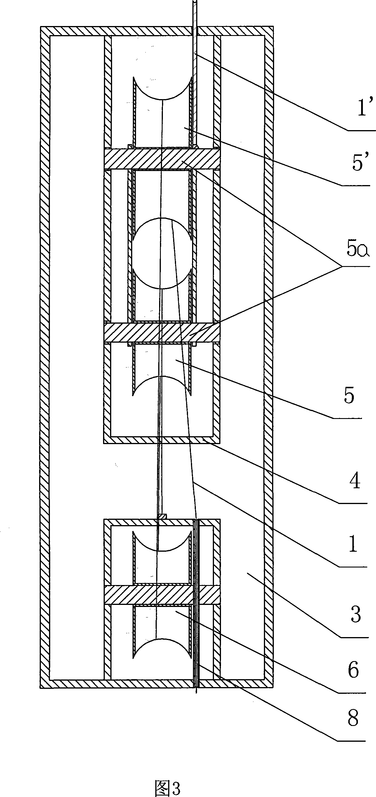
[0030] As shown in Figure 4: the fixed pulley block is composed of the first fixed pulley 6 and the second fixed pulley 6', and is located at one end of the pulley positioning box 3, and the movable pulley block is composed of the first movable pulley 5, the second movable pulley 5 'and the third movable pulley 5", and is located at the other end of the pulley positioning box 3, after the pedal cable 1 extends from one end of the fixed pulley block into the pulley positioning box 3, it goes around the third movable pulley 5" in turn , the second fixed pulley 6 ', the second movable pulley 5', the first fixed pulley 6, and the first movable pulley 5 are then fixed on the pulley positioning box 3.

[0031] It works as follows: .

[0032] Fix the support 2 on the car body, install the pulley positioning box 3 on the support 2, design the pulley bloc...


PUM


Abstract

The invention discloses a clutch cable separation devices, including cable and pedal bearings, and its characteristics are: a fixed period pulley bearings on the location box, the box set up a pulley positioning pulley, cable referred to pedal through the bearings, pulley position from the above box side to enter into position inside the pulley, and bypass the agencies mentioned in the pulley, the pulley fixed in the position described on the box in the center of bodies referred to the pulley fixed connection from Rafah Cable, the cable separation from the position described in the pulley box out the other end of the pulley location box. The present invention is the dominant effect: simple, compact, small size, cheap, easy to operate soft clutch, the driver brought to the driving comfort.

Description

technical field [0001] The invention belongs to automobile clutch components, in particular to a clutch separation cable device for a mechanical clutch. Background technique [0002] At present, the separation control mechanism of domestic clutch is mainly based on mechanical clutch cable and hydraulic clutch control. The structure of the mechanical clutch cable is simple and the price is cheap. The clutch cable is a wire rope. One end of the wire rope is connected to the pedal at the driver's place, and the other end is connected to the clutch release arm of the car. The position is accurate, the support is fixed on the car body, and the steel wire rope passes through the hole on the support. The structure of the whole mechanical clutch cable is simple and the price is cheap; but the mechanical clutch cable is mainly transmitted by a thin steel rope. , the power is transmitted in a 1:1 ratio, resulting in excessive clutch pedal force. [0003] The disadvantages of domesti...

Claims


Application Information

Patent Timeline
Patent Type & Authority Applications(China)
IPC IPC(8): F16D23/12B60K23/02
Inventor 梁先富
Owner 力帆科技(集团)股份有限公司
Why Eureka
Try Eureka