
Evaporation method of linear evaporation sources and evaporation equipment

An evaporation source, linear technology, applied to the field of evaporation method and evaporation equipment of the online evaporation source, can solve the problems of mechanical aging of the evaporation system, low utilization rate of evaporation materials, long scanning distance of evaporation source, etc. The effect of shortening the scanning path, reducing the mechanical loss, and improving the use efficiency

Inactive Publication Date: 2018-04-03
合肥欣奕华智能机器股份有限公司
View PDF8 Cites 0 Cited by
  • Summary
  • Abstract
  • Description
  • Claims
  • Application Information

AI Technical Summary

Problems solved by technology

[0004] The embodiment of the present invention provides a linear evaporation source evaporation method and evaporation equipment, which are used to solve the problems in the prior art, such as the low utilization rate of evaporation materials caused by the long scanning distance of the evaporation source and the problems of the evaporation system. The problem of mechanical aging

Method used


Image

  • Evaporation method of linear evaporation sources and evaporation equipment
  • Evaporation method of linear evaporation sources and evaporation equipment
  • Evaporation method of linear evaporation sources and evaporation equipment

Examples


Embodiment Construction

[0039] Aiming at the problems in the prior art of low utilization rate of evaporation materials and mechanical aging of the evaporation system due to the long scanning distance of the evaporation source, an embodiment of the present invention provides an evaporation method for a linear evaporation source and evaporation equipment.

[0040] The specific implementation of a linear evaporation source evaporation method and evaporation equipment provided in the embodiments of the present invention will be described in detail below in conjunction with the accompanying drawings. The size and shape of each component in the drawings do not reflect the real scale, but are only intended to schematically illustrate the contents of the present invention.

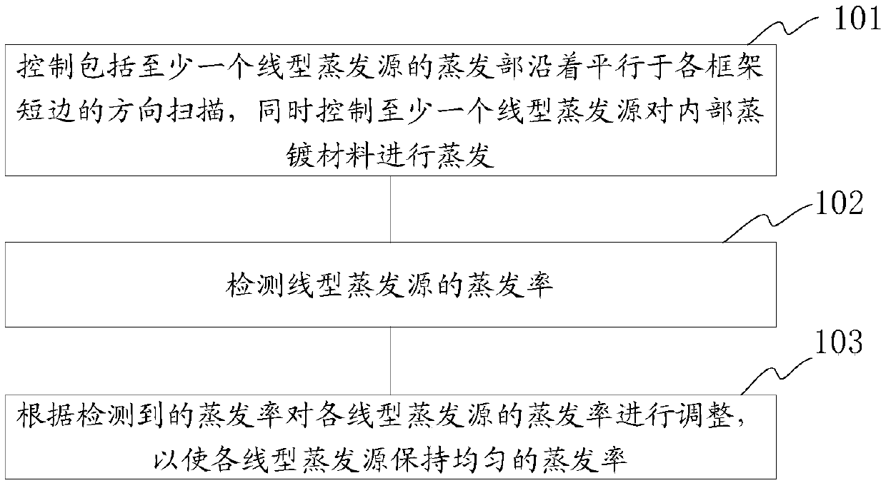
[0041] The embodiment of the present invention provides an evaporation method of a linear evaporation source, such as figure 1 shown, including:

[0042] S101. Control the evaporation part including at least one linear evaporation sou...


PUM


Abstract

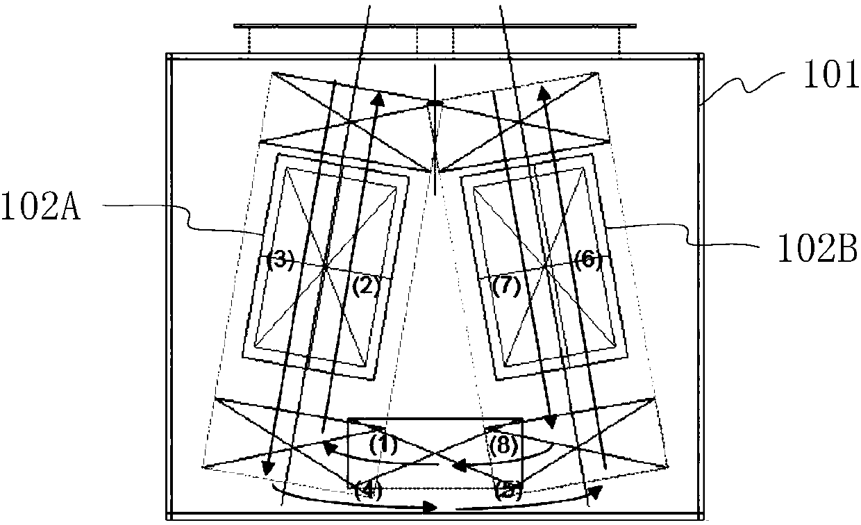
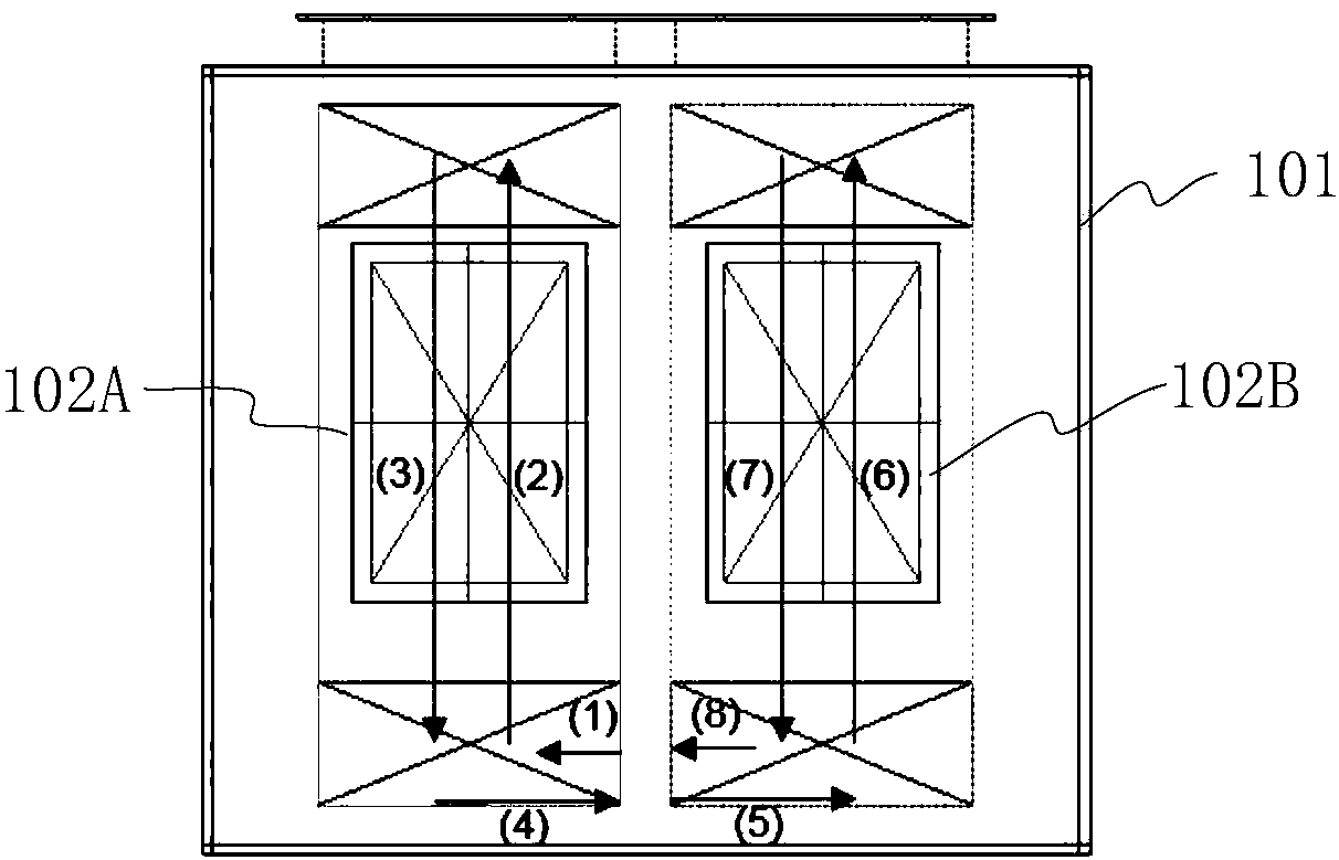
The invention discloses an evaporation method of linear evaporation sources and evaporation equipment. An evaporation part comprising at least one linear evaporation source is controlled to conduct scanning in the direction parallel to short edges of all frames, and meanwhile, the at least one linear evaporation source is controlled to conduct evaporation on internal evaporation materials; and base plates to be subject to evaporation are fixed to the frames, and the length of the linear evaporation sources is larger than or equal to the length of long edges of the base plates to be subject toevaporation. According to the evaporation method of the linear evaporation sources in the embodiment, the evaporation part is controlled to conduct scanning in the direction parallel to the short edges of all frames, the scanning path of the evaporation part is shortened, and therefore the scanning time of the evaporation part can be shortened, the mechanical loss of the evaporation equipment is reduced, and the using efficiency of the evaporation material is improved.

Description

technical field [0001] The invention relates to the technical field of manufacturing display devices, in particular to an evaporation method and evaporation equipment for a linear evaporation source. Background technique [0002] Organic Light-Emitting Diode (OLED) is a device that uses an organic thin film layer that forms a p-n junction to combine the holes (Hole) injected into the anode and the electrons (Electron) in the cathode to emit light. Lightweight, good flexibility, wide viewing angle, low power consumption and other advantages, it is a new generation of display technology with great development prospects. When making an OLED device, a transparent ITO (Indium Tin Oxide) electrode layer that acts as an anode, multiple organic layers with different transport capabilities, and a metal electrode layer that acts as a cathode are sequentially formed on a glass substrate. Among them, the organic layer includes: hole injection layer (HIL), hole transport layer (HTL), li...

Claims


Application Information

Patent Timeline
IPC IPC(8): C23C14/24C23C14/54
CPCC23C14/24C23C14/54
Inventor 裴泳镇李浩永金熏金甲锡
Owner 合肥欣奕华智能机器股份有限公司
Learn More