Supercharge Your Innovation With Domain-Expert AI Agents!

Float glass lehr air-cooled device

A technology of air-cooling device and float glass, which is applied in the field of air-cooling device to achieve the effects of simplified pipeline system, convenient maintenance and superior control effect

Inactive Publication Date: 2007-11-28
CHINA TRIUMPH INT ENG +1
View PDF0 Cites 7 Cited by
  • Summary
  • Abstract
  • Description
  • Claims
  • Application Information

AI Technical Summary

Problems solved by technology

Each primary header can be provided with a control valve

Method used


Image

  • Float glass lehr air-cooled device
  • Float glass lehr air-cooled device
  • Float glass lehr air-cooled device

Examples


Embodiment approach

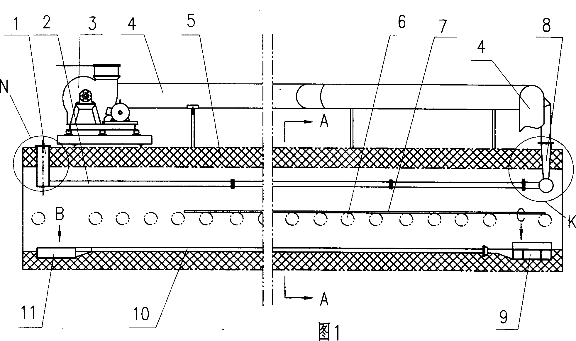
[0024] Specific embodiments: as shown in Figure 1, the annealing kiln 5 is an all-steel structure, and an insulating material is provided in its interlayer, and a group of rollers 6 are arranged inside the annealing kiln 5 to form a glass roller table, and the annealed glass 7 is placed on the glass roller. Move right on the road. On the upper part of the annealing kiln 5, there are 4-6 groups of small air pipes 2, and the left end of each group of small air pipes 2 is respectively connected with the upper wind collecting pipe 1 arranged on the kiln body. The specific structure is shown in Fig. 7 and Fig. 8 , a total of 6 groups of small air ducts, the number of each group of small air ducts 2 is 6-12, and each group of small air ducts 2 is connected to the upwind summarizing pipe 1 after summarizing on the left side, and the top of the upwind summarizing pipe 1 is provided with a filter 1a to prevent debris from entering. Returning to Fig. 1, the other end of each group of s...


PUM


Abstract

The forced air cooling apparatus for float glass annealing kiln includes two fans set in the top of the kiln, air pipeline connected between the fans, three gate valves in the pipeline, one to main air pipe, one first collecting pipe led out from the annealing kiln, one second collecting pipe connected to the first collecting pipe, one lower main air pipe and one bottom transverse distributing pipe connected together. The present invention has the advantages of capacity of controlling the two fans separately with the gate valves, easy control of temperature inside kiln, simplified pipeline system and lowered heat energy loss.

Description

Technical field: [0001] The invention relates to an air cooling device for controlling the temperature in a float glass annealing kiln. Background technique: [0002] The air cooling device of the existing float glass annealing kiln is to install a special fan room below the floor of the workshop, which is connected with the internal air duct of the annealing kiln through the opening on the workshop floor, so its civil structure is complicated and the annealing The external air duct network of the kiln is huge and the energy loss is large. An extensive search for the above problems has not found an effective solution. Invention content: [0003] The purpose of the present invention is to provide a float glass with simple and practical structure, convenient and reliable temperature control and easy maintenance in order to solve the defects of complex civil structure, large air pipe network outside the return kiln and large energy loss in the prior art Annealing kiln air c...

Claims


Application Information

Patent Timeline
Patent Type & Authority Applications(China)
IPC IPC(8): C03B25/00
Inventor 彭寿张仰平王川申刘锐茆令文孙奇程明葛承全辛俊俐王四清左泽方
Owner CHINA TRIUMPH INT ENG
Features
  • R&D
  • Intellectual Property
  • Life Sciences
  • Materials
  • Tech Scout
  • Unparalleled Data Quality
  • Higher Quality Content
  • 60% Fewer Hallucinations
Learn More