Method and device for producing single yarn on operation unit of rotor spinning machine

A rotor spinning machine and operating unit technology, which is applied in the field of single yarn spinning, can solve the problems of affecting the length of the tail yarn, the quality of the joint, and the inability to control the speed of yarn drafting or winding, etc., so as to improve the synchronization Effect

Inactive Publication Date: 2007-11-28
RIETER CZ AS
View PDF1 Cites 17 Cited by
  • Summary
  • Abstract
  • Description
  • Claims
  • Application Information

AI Technical Summary

Problems solved by technology

[0005] The disadvantage of the prior art devices is that the start of the yarn drafting and the start of the yarn winding do not cooperate satisfactorily, which may affect the length of the tail yarn moving down into the spinning rotor and cannot control the spinning-in process The speed at which the yarn is drawn or wound, as a result, will not guarantee the most suitable time sequence for achieving the above operations in all conditions
Due to this shortcoming, the quality of the joints can be negatively affected

Method used


Image

  • Method and device for producing single yarn on operation unit of rotor spinning machine
  • Method and device for producing single yarn on operation unit of rotor spinning machine
  • Method and device for producing single yarn on operation unit of rotor spinning machine

Examples


Embodiment Construction

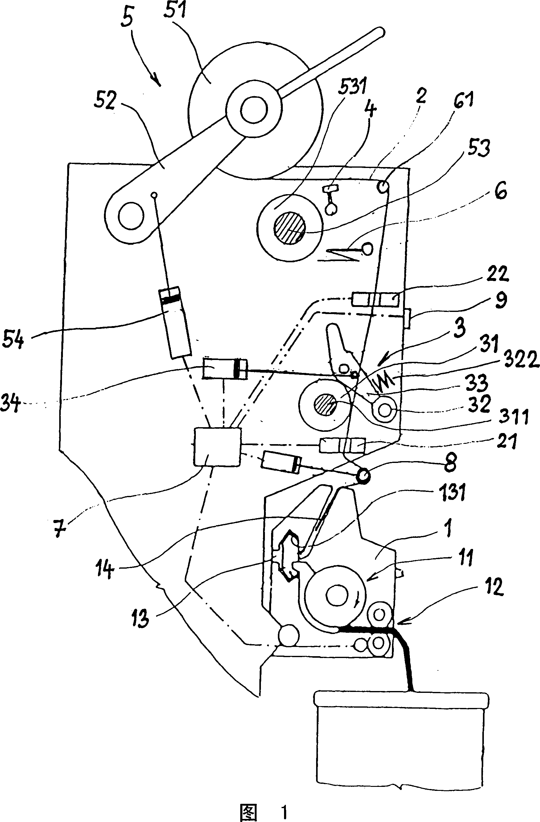
[0023] A rotor spinning machine comprises a number of operating units arranged side by side, each operating unit representing a combined device which independently produces a yarn from a sliver of textile fibers and winds the produced yarn onto a bobbin.

[0024] Each operating unit includes a spinner 1 whose main components are a sliver feeding device 12 , a carding device 11 , a spinning rotor 13 with a condensation groove 131 and a yarn delivery tube 14 .

[0025]A yarn quality and yarn presence sensor 21 and a drafting device 3 thereon are arranged above the spinning box 1 . In the illustrated embodiment, above the drafting device 3 there is a sensor 22 for detecting the presence of yarn, a sensor for detecting the quality and presence of yarn may be arranged. Arranged above the sensor 22 are a yarn distribution device 4 and a yarn winding device 5 in which the final winding bobbin 51 is mounted.

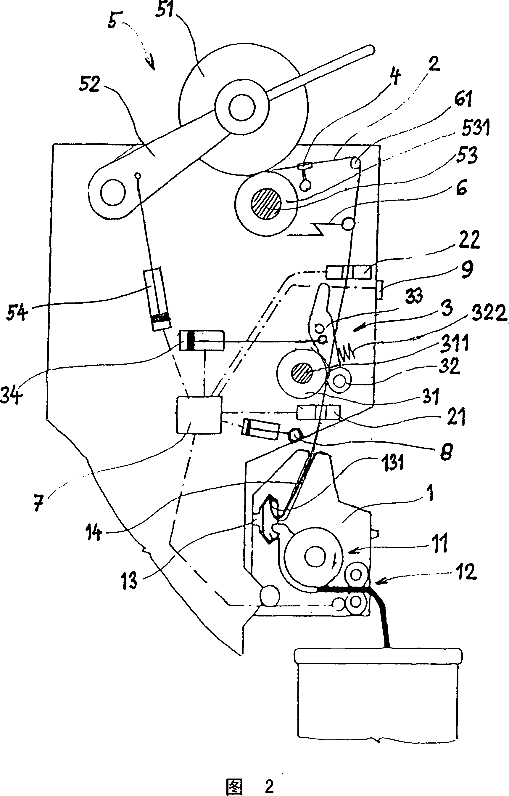
[0026] A first embodiment of the invention is shown in FIGS. 1 and 2 .

...


PUM


Abstract

The invention provides a method and device for individual yarn spinning at spinning station of a rotor spinning machine. During the process of spinning, the yarn is effected in turn by a drafting device (3) independently controlling the yarn and a takeup device (5) independently controlling the yarn.

Description

technical field [0001] The invention relates to a method for spinning-in a single yarn on an operating unit of a rotor spinning machine by means of the operating unit. Furthermore, the invention relates to an individual spinning-in device for an operating unit of a rotor spinning machine, each operating unit of such a rotor spinning machine comprising a spinning unit with There is a feeding device for feeding the sliver into the spinning rotor of the spinning machine, which is connected to a control unit, above which a yarn drafting device (draw-off) is arranged with a continuous The drafting roller on the drafting shaft and the pressing roller installed on the rotary pressing bar connected to a control unit, above the above drafting device is provided with a winding device with a bobbin, which is connected to a control unit, and at the same time in the operating unit There is a yarn deflection device, which connects a control unit and the holding parts and devices of the mac...

Claims


Application Information

Patent Timeline
Patent Type & Authority Applications(China)
IPC IPC(8): D01H4/48
Inventor V・库比斯J・卢德维塞克
Owner RIETER CZ AS
Why Eureka
Try Eureka