Turbine blade structure

a turbine blade and blade technology, applied in the field of turbine blades, can solve the problems of uniform quality of cast products, and achieve the effect of reducing quality variations

Active Publication Date: 2011-06-16
MITSUBISHI POWER LTD
View PDF6 Cites 4 Cited by
  • Summary
  • Abstract
  • Description
  • Claims
  • Application Information

AI Technical Summary

Benefits of technology

[0011]The present invention has been conceived in light of the above situation, and an object thereof is to provide a turbine blade structure that is capable of suppressing the quality variation of cast products during the manufacturing of a turbine blade.
[0014]With such a turbine blade structure, because partition members are provided, partitioning the insides of the cavities located in the central portion of the blade, excluding the blade leading-edge side and the blade trailing-edge side, into the blade pressure side and the blade suction side substantially along the center line, and because the blade leading-edge end portions and the blade trailing-edge end portions of the partition members are inserted from one shroud surface side to the other shroud surface side along the engagement grooves formed on the rib members, the partition members that partition the insides of the cavities and the air foil including the rib members are manufactured as separate pieces having a structure where the partition members manufactured as a separate pieces are attached afterwards; thus, it is possible to keep the quality variations small during the manufacturing of a turbine blade compared with a turbine blade structure whose partitions having the identical function are one-piece molded by precision molding.
[0015]In this case, it is preferable that the partition members be provided with spring structures, thereby making it possible to absorb the thermal stress and pressure fluctuation occurring due to a temperature difference between the inside and the outside of the cavity.
[0017]According to the present invention described above, it is possible to reduce the quality variations during the manufacturing of the turbine blades, because the partition members are structured as separate pieces, which are inserted and fixed into the engagement grooves.

Problems solved by technology

In the case of the turbine blade structure disclosed in Patent Document 3 in particular, there is a problem in that the quality of cast products may not be uniform as a result of a delayed cooling rate due to a relatively large wall thickness, compared with the other nearby blade wall portions, in intersecting portions (for example, cross-shaped portions and T-shaped portions) between the central partition provided along the blade center line from the blade leading-edge side to the blade trailing-edge side and rib members provided to partition the space between the blade pressure side and the blade suction side into a plurality of cavities.

Method used


Image

  • Turbine blade structure
  • Turbine blade structure
  • Turbine blade structure

Examples


Embodiment Construction

[0040]An embodiment of a turbine blade according to the present invention will be described below based on the drawings.

[0041]As shown in FIG. 6, a gas turbine 1 includes, as main elements, a compression unit (compressor) 2 that compresses combustion air, a combustion unit (combustor) 3 that generates high-temperature combustion gas by injecting fuel into the high-pressure air sent from this compression unit 2 thereby causing its combustion, and a turbine unit (turbine) 4 that is positioned downstream of this combustion unit 3 and that is driven by the combustion gas ejected from the combustion unit 3.

[0042]A turbine blade structure according to this embodiment can be applied to, for example, a first-stage vane in the turbine unit 4.

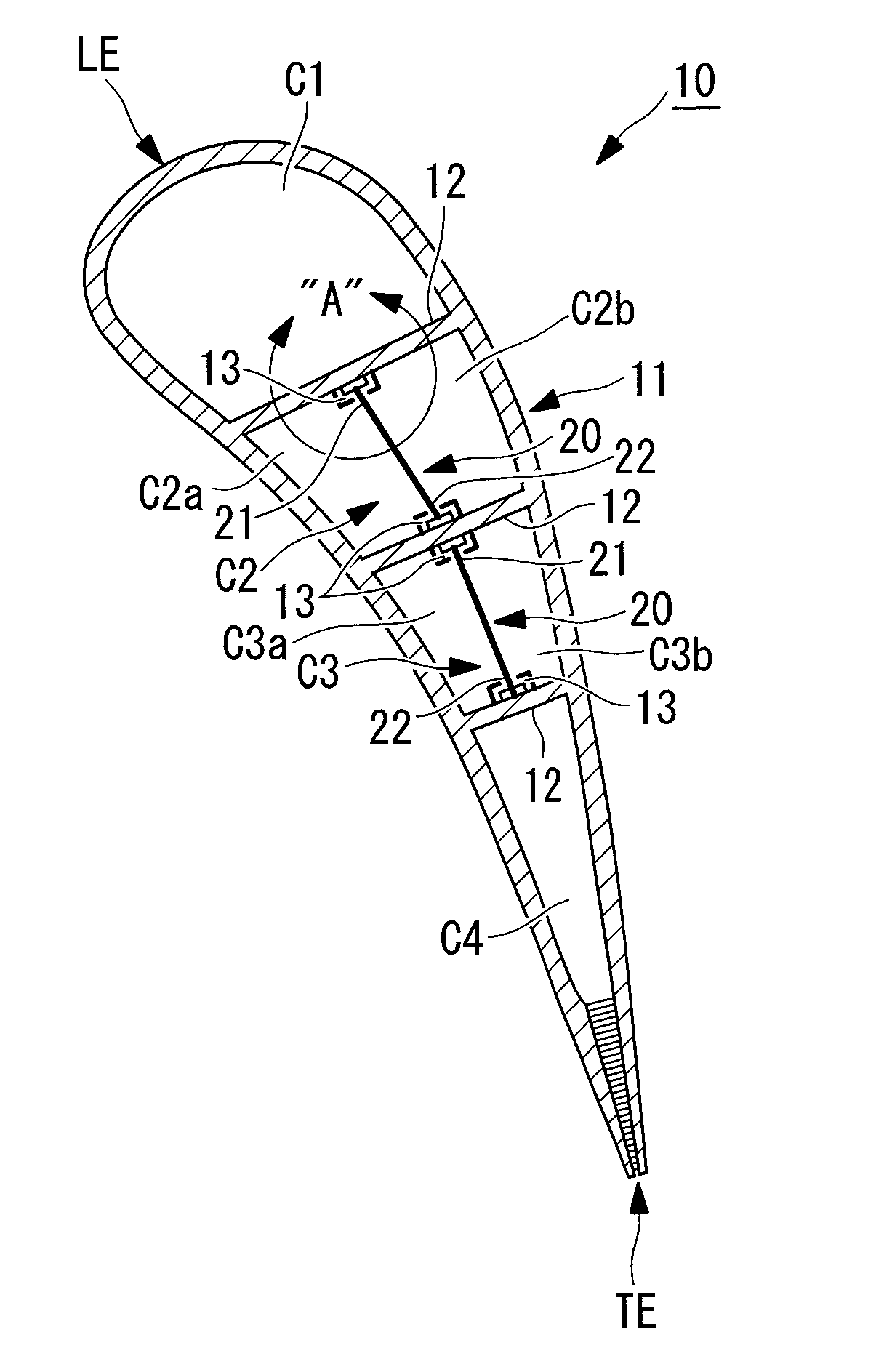
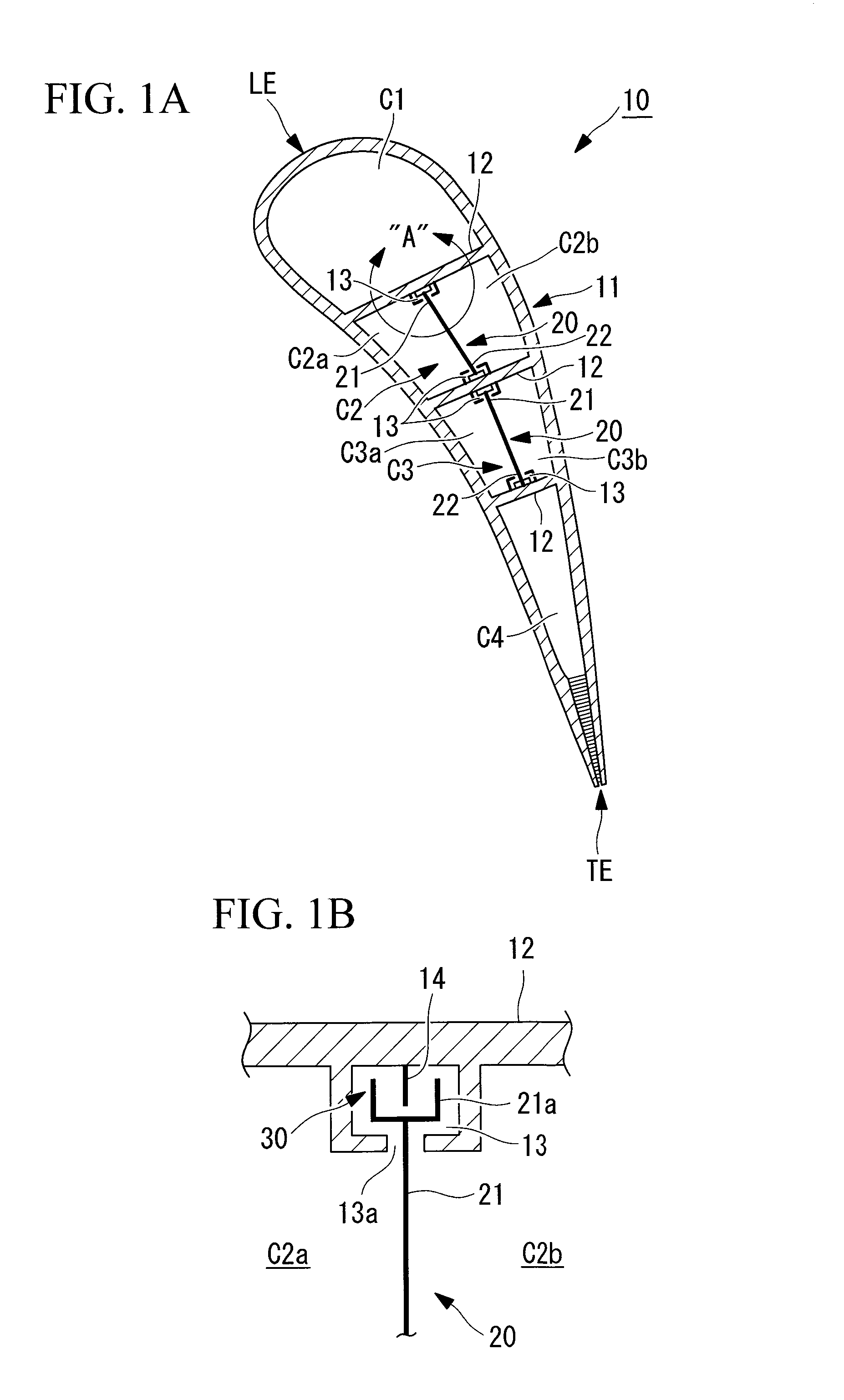
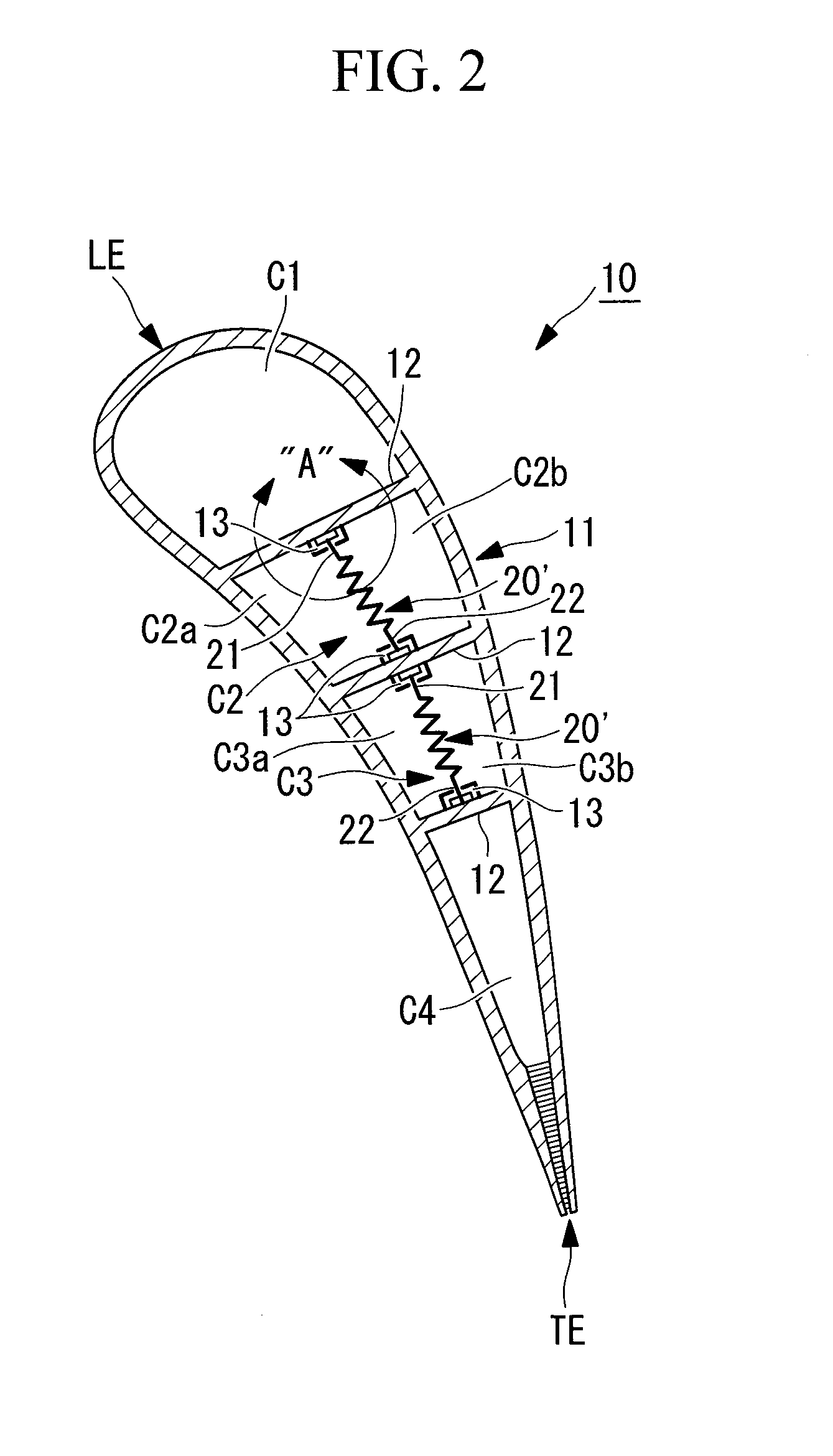
[0043]FIG. 1A shows one example of a turbine blade structure according to a first embodiment. That is, FIG. 1A shows the internal structure of the first-stage vane (“vane” hereafter) 10 of the turbine unit 4 in cross-section. This cross-section is taken ...


PUM


Abstract

Provided is a turbine blade structure that is capable of suppressing quality variations of cast products during the manufacturing of turbine blades. A turbine blade structure wherein the space inside an air foil is divided into a plurality of cavities, partitioned by rib members provided substantially perpendicular to the center line connecting a leading edge and a trailing edge, is provided with partition members that partition the inside of the cavities located in the central portion of the blade, excluding the blade leading-edge side and the blade trailing-edge side, into blade pressure side cavities and blade suction side cavities substantially along the center line, wherein blade leading-edge end portions and blade trailing-edge end portions of the partition members are inserted from one shroud surface side to the other shroud surface side along engagement grooves formed on the rib members.

Description

TECHNICAL FIELD[0001]The present invention relates to a turbine blade (blade, vane) structure of a gas turbine.BACKGROUND ART[0002]Conventionally, in a gas turbine employed in power generation and the like, because high-temperature, high-pressure combustion gas passes through a turbine portion, cooling a turbine vane and the like has been important in order to maintain stable operation.[0003]With respect to a blade of a gas turbine, an air passageway sectional shape that is capable of exhibiting a high cooling capability by air-cooling has been proposed. In this case, with an air passageway sectional shape wherein the cooling air flows toward the tip of the blade, the shape thereof is such that an edge on the airfoil pressure surface side is longer, whereas with an air passageway sectional shape wherein the cooling air can flow toward the basal end of the blade, the shape thereof is such that an edge on the airfoil suction surface side is longer (for example, see Patent Document 1)....

Claims


Application Information

Patent Timeline
Patent Type & Authority Applications(United States)
IPC IPC(8): F01D9/02
CPCF01D5/16F05D2260/941F05D2260/94F01D5/188F01D5/18F01D5/26F01D25/00
Inventor TSUKAGOSHI, KEIZOHASHIMOTO, TOMOKOHADA, SATOSHI
Owner MITSUBISHI POWER LTD
Why Eureka
Try Eureka