
Multiple tubular pile type bar-free gas-production oil-production method and device

A technology of oil production equipment and composite pipe, which is applied in the direction of production fluid, earthwork drilling, wellbore/well parts, etc., can solve the problems of frequent operation, difficult operation, cavitation, etc., and achieve the solution of eccentric wear and production cost of oil and water wells Low, avoid low-efficiency effects

Inactive Publication Date: 2007-11-28
安之玉
View PDF0 Cites 10 Cited by
  • Summary
  • Abstract
  • Description
  • Claims
  • Application Information

AI Technical Summary

Problems solved by technology

[0002] Traditional gas recovery methods and equipment are mainly traditional downhole pipe strings and deep well pumps, electric submersible pumps, and screw pumps. These oil recovery pumps have made or are making contributions to the recovery of oil, gas and water, but they also have Their respective shortcomings or deficiencies: ①Deep well pumps are prone to cavitation in gas wells, and eccentric wear between pipes and rods, resulting in low efficiency and large energy loss. It cannot be used on the well; ②The electric submersible pump goes down to the bottom of the well and the cable and pump are easily damaged by wear and tear. Once damaged, the pump is stopped and it is difficult to start it again.
In addition, when the liquid supply in the formation is insufficient, it is easy to generate heat and burn out the impeller, guide wheel and other components; ③The downhole starting method of the screw pump also has the same or similar shortcomings or deficiencies as the electric submersible pump; ④The water level in the wellbore When it is high, the gas will be suppressed, the gas production efficiency will be low, or even no gas will be produced, resulting in frequent operations and increased production costs

Method used


Image

  • Multiple tubular pile type bar-free gas-production oil-production method and device

Examples


Embodiment Construction

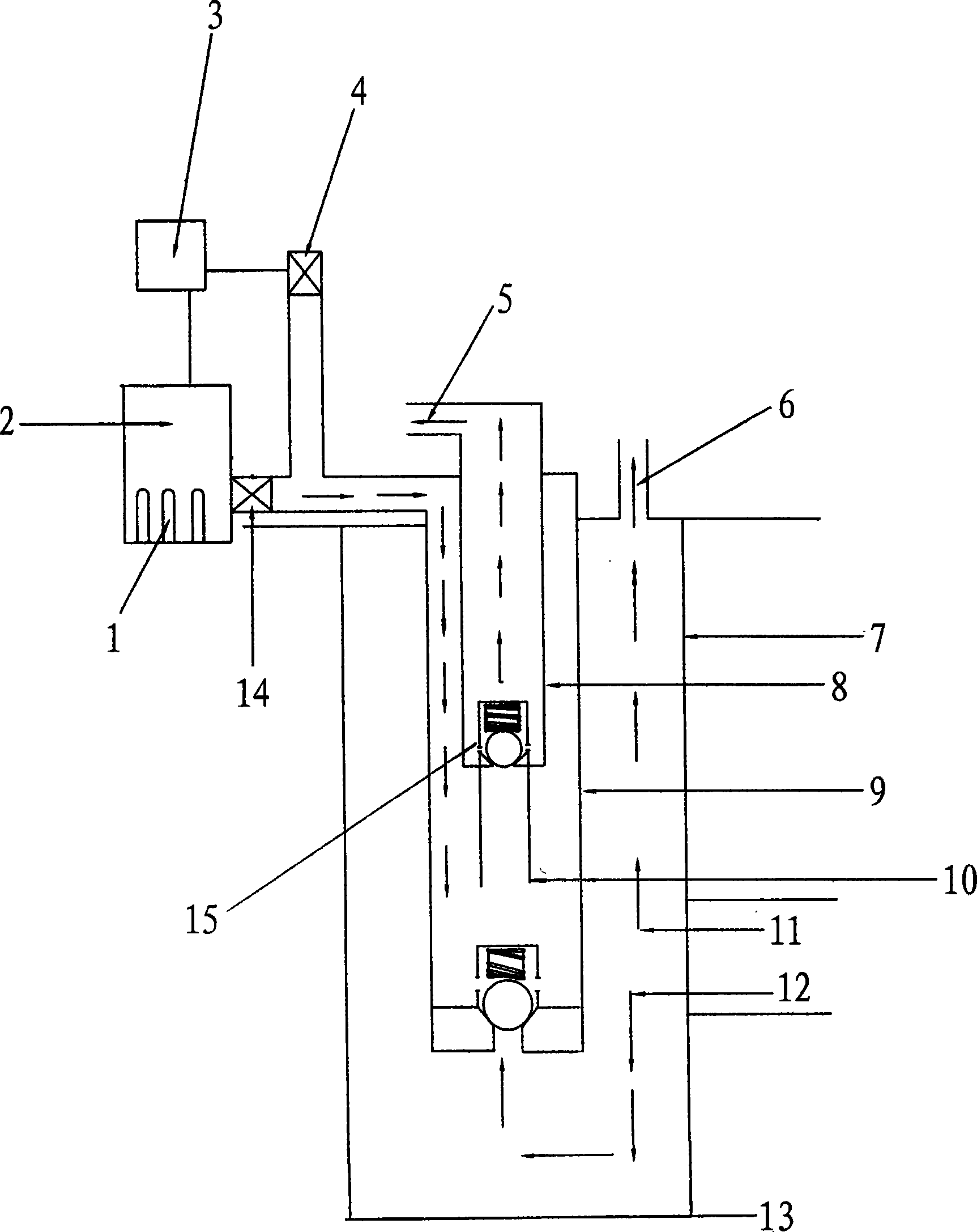
[0017] A composite string-type rodless gas recovery and oil recovery method, including gas recovery and oil recovery from deep wells, gas recovery and oil recovery from deep wells is carried out by using a gas injection device and a composite tube string for oil recovery and water recovery, that is to say, from the wellhead through injection The gas device injects gas into the composite pipe string for oil production and water production in the well, and discharges the accumulated water in the well from the composite pipe string for oil production and water production. The natural gas in the well is produced from the annulus of the oil casing. Extracted from.

[0018] The gas injection of the wellhead gas injection device into the oil production and water production composite pipe string in the well is an annular space injection between the outer oil pipe and the inner oil pipe of the self-production oil and water production composite pipe string for intermittent gas injection....


PUM


Abstract

The invention relates to a compound pipe-column no-rod gas and oil production method, comprising gas and oil are produced from the deep well. Gas and oil production from the deep well is carried out by adopting gas injection device and compound pipe-column, namely in gas production by gas injection device gas is injected in the compound pipe-column in well from the well head; waterlogging in well is discharged from the compound pipe-column; natural gas in well is exploited from the oil casing annular; in oil production oil water is discharged from the oil and water compound pipe-column. The compound pipe-column no-rod gas and oil production device comprises gas injection device and oil and water production compound pipe-column the oil and water production compound pipe-column comprises outer oil pipe and inner oil pipe set in the sleeve pipe of oil well. Unidirectional valve is set at the lower end of inner oil pipe and the upper end is the outlet of oil water. Unidirectional valve is set at the lower end of outer oil pipe and the upper end is connected with the gas injection device. The gas injection device comprises electromagnetic switch connected on the outer oil pipe, electromagnetic relief valve, compressor, energy accumulator and air storing tank connected with the compressor and the electromagnetic relief valve.

Description

1. Technical field [0001] The invention relates to a method and equipment for extracting oil, gas, and water from wells, in particular to a method and device for composite string type rodless gas extraction and oil extraction. 2. Background technology [0002] Traditional gas recovery methods and equipment are mainly traditional downhole pipe strings and deep well pumps, electric submersible pumps, and screw pumps. These oil recovery pumps have made or are making contributions to the recovery of oil, gas and water, but they also have Their respective shortcomings or deficiencies: ①Deep well pumps are prone to cavitation in gas wells, and eccentric wear between pipes and rods, resulting in low efficiency and large energy loss. It cannot be used on the well; ②The electric submersible pump goes down to the bottom of the well, and the cable and pump are easily damaged by wear and tear. Once damaged, the pump is stopped and it is difficult to start it repeatedly. In addition, wh...

Claims


Application Information

Patent Timeline
IPC IPC(8): E21B43/00
Inventor 安之玉
Owner 安之玉
Learn More