Light source illumination system

A lighting system and light source technology, which is applied to lighting devices, lighting and heating equipment, cooling/heating devices for lighting devices, etc. Effect

Inactive Publication Date: 2007-11-28
曹嘉灿
View PDF0 Cites 24 Cited by
  • Summary
  • Abstract
  • Description
  • Claims
  • Application Information

AI Technical Summary

Problems solved by technology

[0003] As a new light source, LED is small in size and light in weight, and has many advantages, but it has relatively high requirements

Method used


Image

  • Light source illumination system
  • Light source illumination system
  • Light source illumination system

Examples


Example Embodiment

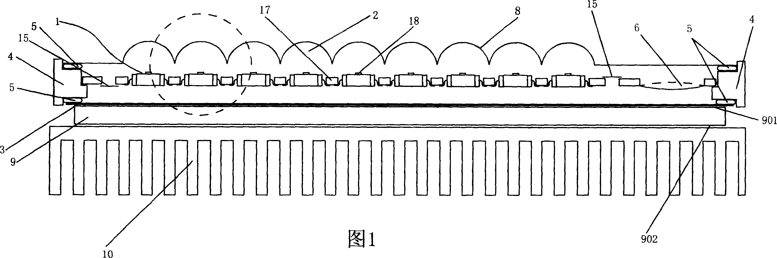
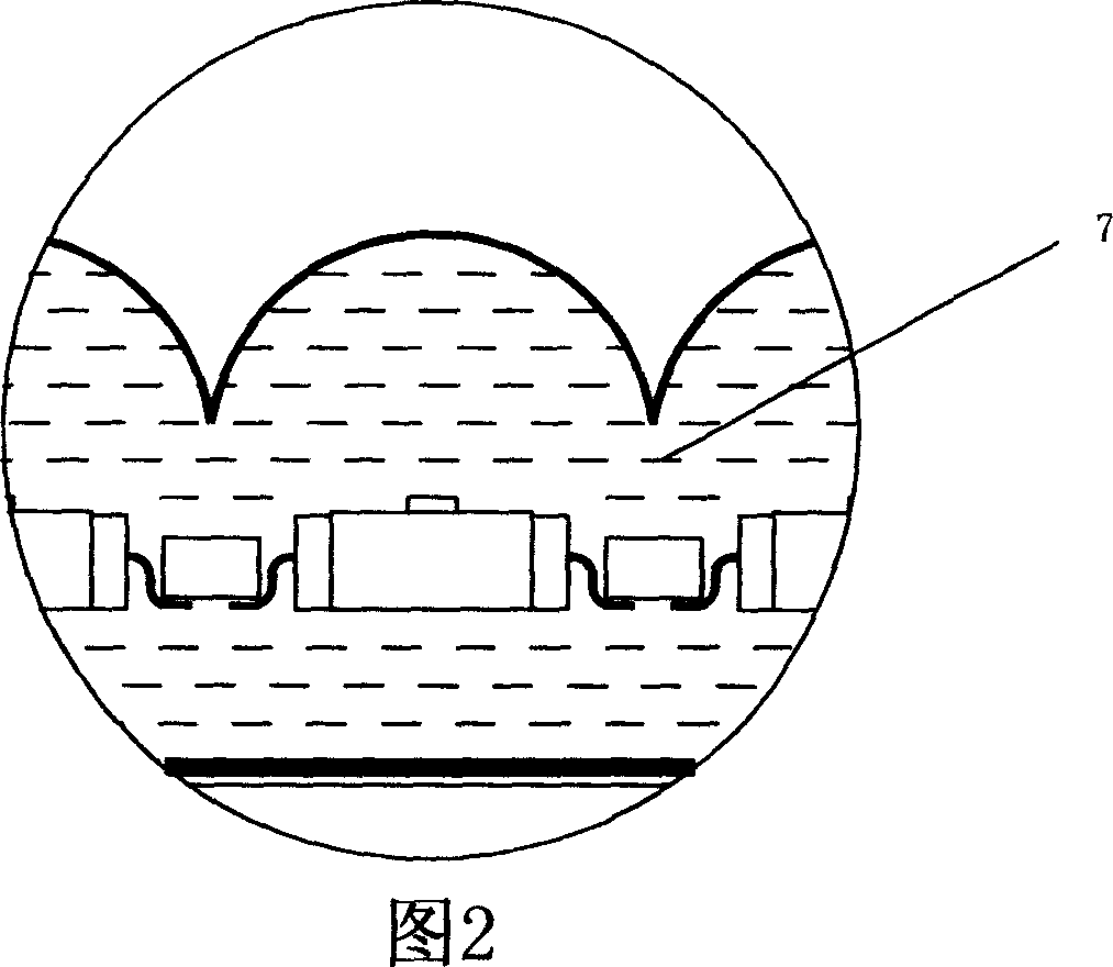
[0025] As shown in FIG. 1, it is a schematic structural diagram of the first embodiment of the light source lighting system of the present invention. The specific structure of this embodiment is described with reference to the partial enlarged view of FIG. 1 shown in FIG. 2. The light source lighting device includes an LED array 1. In this embodiment, the plurality of LED chips 18 in the LED array 1 are mounted together through the PCB board 17 , and the lens array 2 matched with the LED array 1 is used to parallel or parallel the light emitted by the LED array 1 . Divergently launched. A sealing base 4 is arranged around the lens array 2 and the heat-conducting plate 3, and a sealing gasket 5 is arranged at the sealing base 4 to form a sealed container. The LED array 1 is sealed in the sealing formed by the lens array 2 and the heat-conducting plate 3. Between the containers, a sealed container is filled with a transparent cooling liquid 7, and the sealed container is also fi...


PUM


Abstract

The invention relates to a lighting system of light source, comprising lighting device of light source. The lighting system of light source also comprises semiconductor cooler for cooling said lighting device of light source. The cooling surface of said semiconductor cooler is contacted with the light device of light source. Because the lighting system of light source in invention adopts semiconductor cooler to cool and cooling liquid is added in the LED chip, the dissipation of LED chip is better and small high-brightness projector can be obtained.

Description

technical field [0001] The present invention relates to a light source device, and more particularly, to a projector having the light source device. Background technique [0002] Traditional projectors have always used halogen lamps and high-pressure mercury lamps as their light sources. These light sources have their limitations. The life of halogen lamps is short. It hinders the small size and light weight of the projector. Although the life of the high-pressure mercury lamp is longer than that of the halogen lamp, it is still short-lived, and it takes a long time to start. [0003] As a new light source, LEDs are small in size and light in weight, and have many advantages, but they have relatively high requirements on the working environment, especially on temperature, and the existing technology cannot solve the problem of LED heat dissipation well. SUMMARY OF THE INVENTION [0004] The technical problem to be solved by the present invention is to provide a novel lig...

Claims


Application Information

Patent Timeline
IPC IPC(8): F21V29/00F21V29/508F21V29/56
Inventor 曹嘉灿
Owner 曹嘉灿
Why Eureka
Try Eureka