Lighting device

A light-emitting device and light-emitting element technology, which is applied in the direction of electrical components, electric solid-state devices, circuits, etc., can solve problems such as poor heat dissipation, difficult heat dissipation, and temperature rise, so as to avoid thermal resistance and aging problems, and reduce production costs. cost and time, and the effect of improving product reliability

Inactive Publication Date: 2007-11-28
DELTA ELECTRONICS INC
View PDF0 Cites 9 Cited by
  • Summary
  • Abstract
  • Description
  • Claims
  • Application Information

AI Technical Summary

Problems solved by technology

[0004] With the development of high efficiency and high brightness of the light-emitting device 1, the light-emitting element 12 will dissipate heat during operation, and the accumulated heat will increase the temperature and cause adverse effects on the luminous efficiency and service life of the light-emitting element 12
However, the conventional light-emitting element 12 is disposed on the insulating layer 11 with poor heat dissipation, and the airtight packaging of the encapsulation layer 14 makes it difficult for the heat emitted by

Method used


Image

  • Lighting device
  • Lighting device
  • Lighting device

Examples


Embodiment Construction

[0036] A light emitting device according to a preferred embodiment of the present invention will be described below with reference to related drawings, wherein the same elements will be described with the same reference symbols.

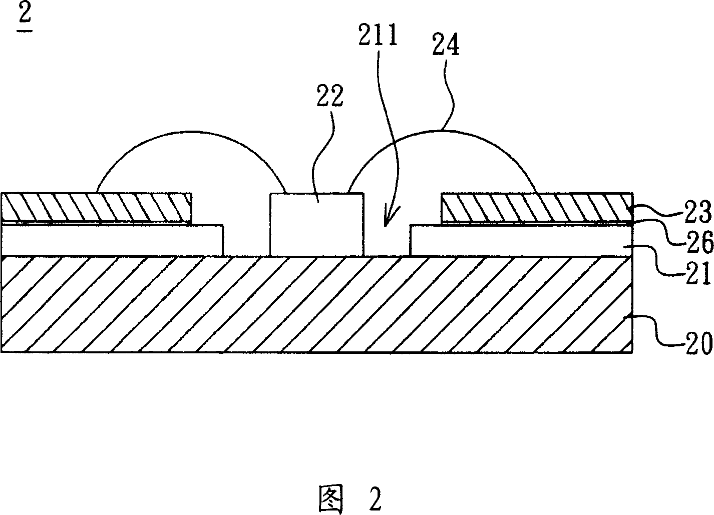
[0037] Referring to FIG. 2 , a light emitting device 2 according to a preferred embodiment of the present invention includes a substrate 20 , an insulating layer 21 and at least one light emitting element 22 .

[0038] In this embodiment, the material of the substrate 20 can be made of at least one of copper, aluminum, magnesium, titanium and alloys thereof to provide better thermal conductivity; in addition, the material of the substrate 20 can also be made of ceramic material or To provide better thermal conductivity, and the substrate 20 can be rigid (rigid) substrate or flexible (flexible) substrate, that is, the shape of the substrate 20 can be flat, curved or Zigzag.

[0039] The insulating layer 21 is disposed on the substrate 20, and the ins...


PUM


Abstract

The invention discloses a luminous device, which comprises the following parts: base, at least one luminous element and insulating layer, wherein the insulating layer is set on the base, which has a pattern exposed out of the base partially; the luminous element is set on the base within the pattern area.

Description

technical field [0001] The invention relates to a light emitting device, in particular to a light emitting device with good heat dissipation performance. Background technique [0002] With the development of the optoelectronic industry, light-emitting elements such as light-emitting diodes (LEDs) have been widely used in display applications of various electronic products. [0003] Please refer to FIG. 1, a conventional LED light emitting device 1 is provided with an insulating layer 11 on a substrate 10, and a plurality of LED light emitting elements 12 are arranged on the insulating layer 11, and then connected with the set in a wirebonding manner. A metal layer 13 on the insulating layer 11 forms an electrical connection, and finally the LED light-emitting elements 12 are covered with an encapsulation layer 14 to protect the light-emitting elements 12 from being damaged by mechanical, heat, moisture or other factors. [0004] With the development of high efficiency and h...

Claims


Application Information

Patent Timeline
IPC IPC(8): H01L33/00H01L23/498H01L33/62
CPCH01L2224/48247H01L2224/48091H01L2924/0002
Inventor 张绍雄陈央嶙
Owner DELTA ELECTRONICS INC
Why Eureka
Try Eureka