Position detection system, guidance system, position detection method, medical device, and medical magnetic-induction and position-detection system

A detection system, a technology of magnetic induction coils, applied in applications, sensors, medical science, etc., can solve problems such as difficulty in reducing capsule size, increased manufacturing cost of capsule-shaped medical devices, and increased number of LC resonant circuits

Inactive Publication Date: 2007-11-28
OLYMPUS CORP
View PDF5 Cites 24 Cited by
  • Summary
  • Abstract
  • Description
  • Claims
  • Application Information

AI Technical Summary

Problems solved by technology

[0010] However, if the capacitance of the capacitor is selected according to the individual LC resonance circuit, the number of manufacturing steps of the LC resonance circuit increases, resulting in a problem that the manufacturing cost of the capsule medical device increases
[0011] In addition, it is difficult to reduce the size of the capsule because the power supply must be used inside the capsule, and because the power supply capacity must be increased
In addition, there is a problem that the working time of the capsule is reduced

Method used


Image

  • Position detection system, guidance system, position detection method, medical device, and medical magnetic-induction and position-detection system
  • Position detection system, guidance system, position detection method, medical device, and medical magnetic-induction and position-detection system
  • Position detection system, guidance system, position detection method, medical device, and medical magnetic-induction and position-detection system

Examples


no. 1 example

[0252] Now, a first embodiment of the medical magnetic induction and position detection system according to the present invention will be described with reference to FIGS. 1 to 13B.

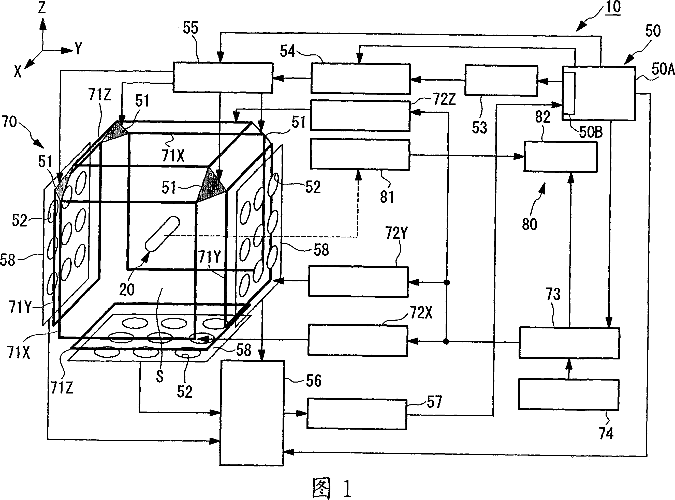
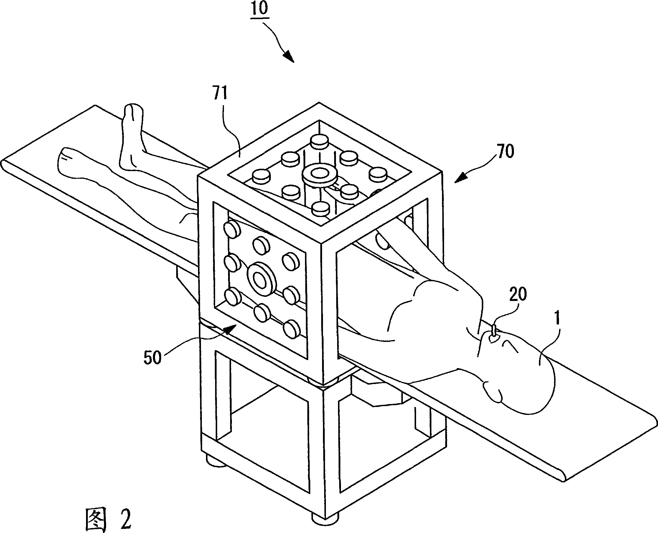
[0253] FIG. 1 is a diagram schematically showing a medical magnetic induction and position detection system according to this embodiment. Fig. 2 is a perspective view of the medical magnetic induction and position detection system.

[0254] As shown in Figures 1 and 2, the medical magnetic induction and position detection system 10 is mainly formed by the following components: a capsule endoscope (medical device) 20, which is introduced into the body cavity of the patient 1 by oral or anal injection to monitor the body cavity The inner surface of the passageway is optically imaged, and the image signal is sent wirelessly; the position detection unit (position detection system, position detector, computing device) 50, which detects the position of the capsule endoscope 20; the magnetic induction d...

no. 2 example

[0441] Now, referring to Figs. 14 and 15, a second embodiment of the present invention will be described.

[0442] The basic configuration of the medical magnetic induction and position detection system according to this embodiment is the same as that of the first embodiment; however, the determination method and determination mechanism of the calculation frequency are different from the case of the first embodiment. Therefore, in this embodiment, referring to FIGS. 14 and 15 , only the determination method and determination mechanism of the calculation frequency will be described, and the description of the magnetic induction device and the like will be omitted.

[0443] Fig. 14 is a diagram schematically showing a medical magnetic induction and position detection system according to this embodiment.

[0444]The same components as those of the first embodiment are denoted by the same reference numerals, and thus will not be described again.

[0445] As shown in FIG. 14 , the...

no. 3 example

[0498] Now, referring to Figs. 19 and 20, a third embodiment of the present invention will be described.

[0499] The basic configuration of the medical magnetic induction and position detection system according to this embodiment is the same as that of the first embodiment; however, the configuration of the position detection unit is different from the case of the first embodiment. Therefore, in this embodiment, only the case in the vicinity of the position detection unit will be described using FIGS. 19 and 20 , and the description of the magnetic induction device and the like will be omitted.

[0500] FIG. 19 is a schematic diagram showing the layout of driving coils and sensing coils of the position detection unit.

[0501] Since other parts of the position detection unit other than the driving coil and the sensing coil are the same as in the case of the first embodiment, their descriptions are omitted.

[0502] As shown in FIG. 19 , the drive coil (drive coil) 251 and se...


PUM


Abstract

There are provided a position detection system, a guidance system, and a position detection method which obviate the need for frequency adjustment of an alternating magnetic field used in position detection of a device and which allow the device to be made more compact and less expensive. There are included a device (capsule endoscope 20 ) provided with a magnetic induction coil, a drive coil 51 for generating an alternating magnetic field, a plurality of magnetic sensors 52 for detecting an induced magnetic field, a frequency determining section 50 B for determining a position calculating frequency based on a resonance frequency of the magnetic induction coil, and a position analyzing unit 50 A for calculating, at the position calculating frequency, at least one of the position and the orientation of the device 20 based on the difference between outputs from the magnetic sensors 52 when only the alternating magnetic field is applied and outputs from the magnetic sensors 52 when the alternating magnetic field and the induced magnetic field are applied; and at least one of a frequency range of the alternating magnetic field and an output frequency range of the magnetic field sensors is limited based on the position calculating frequency.

Description

technical field [0001] The invention relates to a position detection system, a guidance system, a position detection method, a medical device, and a medical magnetic induction and position detection system. Background technique [0002] Recently, swallowable capsule medical devices represented by capsule endoscopes etc., which are swallowed by the patient to enter the patient's body, where they pass through the passage in the body cavity to catch the passage in the body cavity Image of the target location inside. The above-mentioned capsule endoscope has a configuration in which an image forming device (such as a CCD (Charge Coupled Device) that can acquire an image, etc.) that can perform the above-mentioned medical procedure is provided therein, and is performed at a target position inside a channel in a body cavity. Image acquisition. [0003] However, the capsule medical device described above simply moves along the alimentary canal with peristalsis, and the position a...

Claims


Application Information

Patent Timeline
Patent Type & Authority Applications(China)
IPC IPC(8): A61B5/06
CPCA61B1/00147A61B2019/2253A61B5/06A61B1/00158A61B1/041A61B5/7232A61B1/042A61B34/73A61B5/062A61B1/00
Inventor 佐藤良次内山昭夫木村敦志河野宏尚
Owner OLYMPUS CORP
Why Eureka
Try Eureka