Balanced-unbalanced antennas

A technology for balancing antennas and antennas, applied to antennas, resonant antennas, antenna combinations with different interactions, etc., can solve problems such as low efficiency and lack of bandwidth

Inactive Publication Date: 2007-11-28
ANTENOVA LTD
View PDF3 Cites 11 Cited by
  • Summary
  • Abstract
  • Description
  • Claims
  • Application Information

AI Technical Summary

Problems solved by technology

Antennas within the Chu-Harrington limit are less efficient radiators and / or lack sufficient bandwidth

Method used


Image

  • Balanced-unbalanced antennas
  • Balanced-unbalanced antennas
  • Balanced-unbalanced antennas

Examples


Embodiment Construction

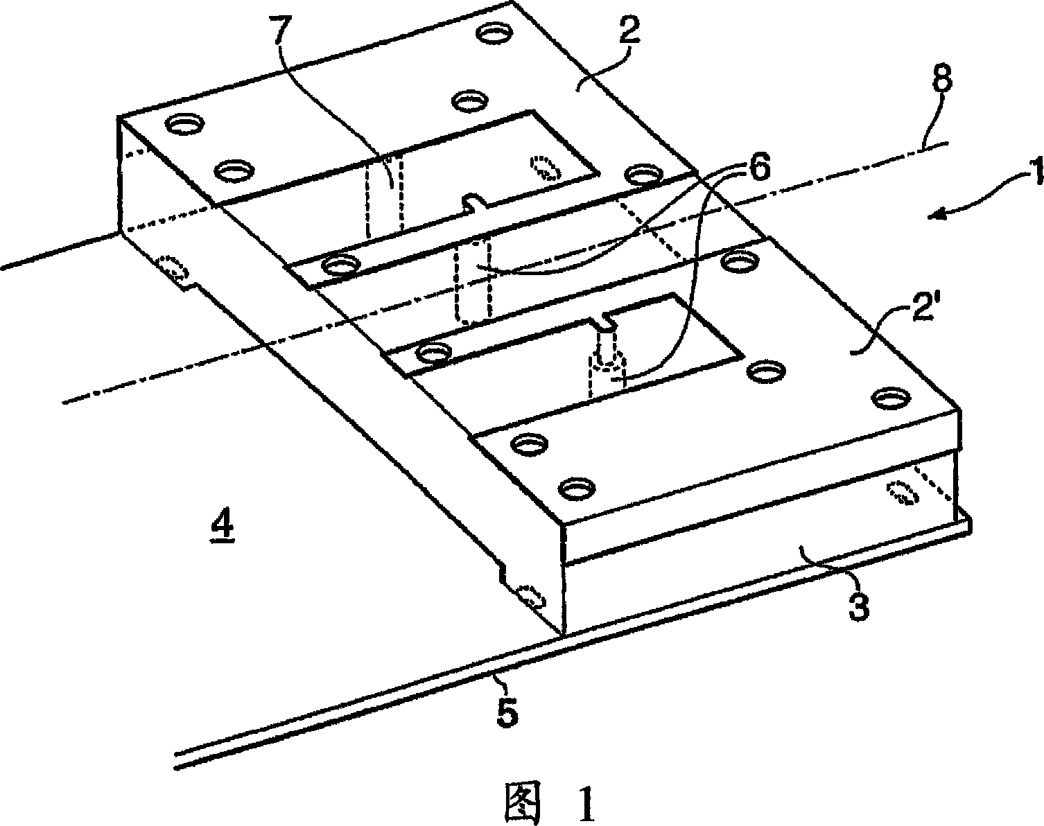
[0098] Figure 1 shows an antenna module 1 comprising a pair of self-complementary PIFAs 2, 2' mounted on a dielectric forming element 3 mounted on a PCB 4 with a conductive ground plane 5 on the underside. Each PIFA 2, 2' has a shorting pin 6 and a feeder 7. The PIFAs 2, 2' are symmetrical about the long axis 8 of the PCB 4. Since each PIFA 2, 2' excites a current in the ground plane 5 opposite to the other PIFA 2, 2', the currents cancel each other out leaving only a very small residual current in the ground plane. In this way, a pair of unbalanced antennas can be driven close to the ground plane.

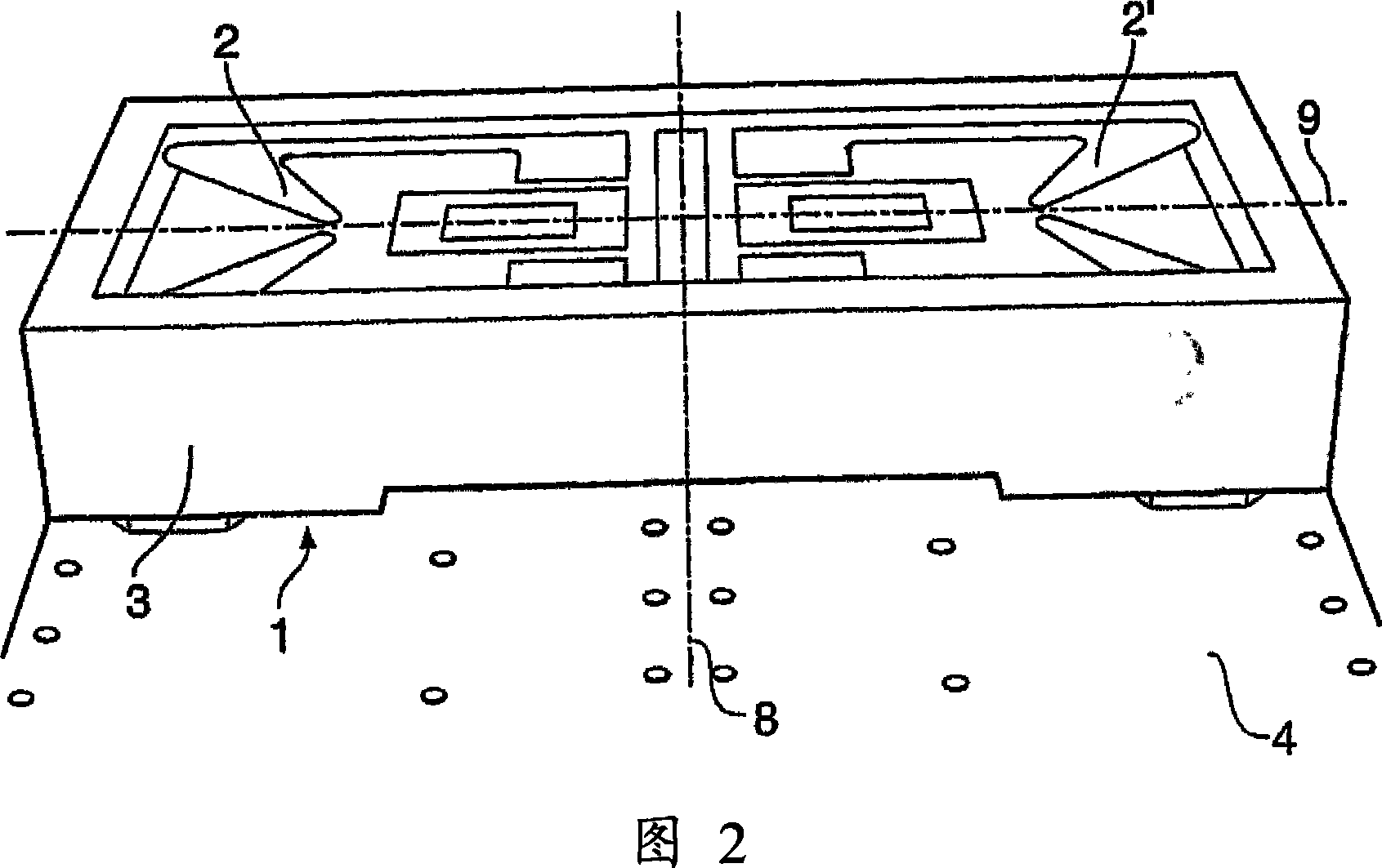
[0099] FIG. 2 shows a variant of the embodiment of FIG. 1 , the like parts of which are referenced in FIG. 1 . The embodiment of Figure 2 has a pair of PIFAs 2, 2' that are doubly symmetrical, i.e. the PIFAs 2, 2' Ground plane currents can be further canceled out by adopting double symmetry (being PIFA 2, 2' and pins 6, 7 (not shown in Figure 2)).

[0100] ...


PUM


Abstract

There is disclosed an antenna device comprising a pair of physically and electrically symmetrical radiating elements configured for cooperative operation as a balanced antenna, and a third radiating element configured for operation as an unbalanced antenna. The balanced antenna may be configured for operation in a first frequency band, and the unbalanced antenna may be configured for operation in a second frequency band. Embodiments of the disclosed antenna device provide multiband operation close to a conductive groundplane and are strongly resistant to detuning.

Description

[0001] This invention relates to antennas, particularly but not exclusively antennas for portable devices. It is applicable to all types of antennas, not limited to PIFA (Planar Inverted-F Antenna), monopole antenna, dielectric antenna, etc. It finds application in a variety of applications, but is particularly, but not exclusively, related to mobile telephone handsets, personal digital assistants (PDAs) and laptop computers. Background technique [0002] Designing the internal antennas of small modern communication devices is notoriously difficult. [0003] First, there are many different types of platforms, especially for handheld devices such as clamshell designs, bar phones, flip phones, sliders and swing phones (swing phone) designs are public. For example, the connection between the two parts of a segmented phone can have a large impact on antenna performance. [0004] Second, modern communication equipment is getting smaller and smaller, but at the same time, antenna...

Claims


Application Information

Patent Timeline
Patent Type & Authority Applications(China)
IPC IPC(8): H01Q21/29H01Q9/04H01Q9/26H01Q5/00H01Q1/24H01Q5/10H01Q5/321H01Q5/35
CPCH01Q1/243H01Q5/0048H01Q5/321H01Q21/29H01Q9/0421H01Q5/0034H01Q5/35H01Q21/30H01Q9/26H01Q1/38H01Q5/00H01Q9/04H01Q21/28H01Q1/24
Inventor 乔纳森·艾德西蒙·菲利普·金斯利史蒂文·格雷戈里·奥基夫塞普·萨里奥戴维斯·莱利斯罗伯特·沃尔特·史努波布赖恩·柯林斯
Owner ANTENOVA LTD
Why Eureka
Try Eureka