
Rotary tool for surface processing

A technology of rotary tool and surface machining, applied in metal processing, manufacturing tools, wheels with flexible working parts, etc., can solve the problems of difficult surface machining, limitations of rotary tools, etc.

Active Publication Date: 2007-12-05
MONTI WERKZEUGE
View PDF3 Cites 1 Cited by
  • Summary
  • Abstract
  • Description
  • Claims
  • Application Information

AI Technical Summary

Problems solved by technology

Non-destructive surface machining is difficult to achieve with this tool
[0005] Known rotary tools for surface machining have proven themselves in principle, but have their limitations not only with regard to the need for careful machining, but also with regard to the need for rapid and in particular efficient machining at the same time

Method used


Image

  • Rotary tool for surface processing

Examples


Embodiment Construction

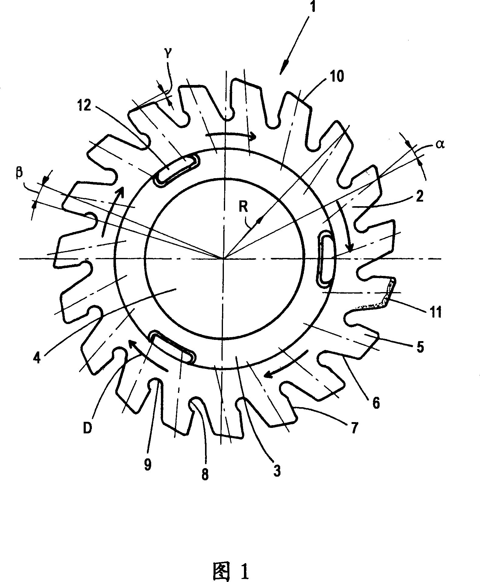
[0023] In the figure, the rotary tools for surface machining are shown in the embodiment as a disc 1 , an annular disc and a foil remover, respectively. Said disc 1 consists of rubber-elastic plastic, in this case polyurethane (PUR). However, it is also possible for only the outer ring 2 to be made of rubber-elastomeric plastic, while the inner ring 3 consists of thermoplastic rubber.

[0024] For machining purposes, the disk 1 has an outer ring 2 and an inner ring 3 for connection to a disk holder 4 that can be driven in rotation and is only shown. The outer ring 2 of the disc 1 has elastically bendable processing teeth 5, which are distributed on the circumference of the disc 1 and stand upright away from the circumference, and the processing teeth 5 are arranged on the outer ring 2 at equal intervals from each other. .

[0025] Each machining tooth 5 has a front machining edge 6 and a rear machining edge 7 . Obviously, the front machining edge 6 and the rear machining ed...


PUM


Abstract

To provide a rotary tool for machining a surface.The rotary tool is preferably equipped with a rubber elastic disk (1) and machining teeth (5) where outer rims (2) are placed at intervals apart from one another, and disposed with an inclination with respect to the radial direction. Respective machining teeth (5) have dimples (8) for forming at least hinges.

Description

technical field [0001] The invention relates to a rotary tool for surface machining with a disc, the outer edge of which is equipped with machining teeth arranged at a distance from each other. Advantageously, the disc is an elastic disc of rubber. In addition, the machining teeth may be radially aligned or have an arrangement inclined with respect to the radial direction. This means that the machining teeth are generally arranged obliquely, but can also extend radially. Background technique [0002] Such a rotary tool is described in German patent DE 202 03 009 U1. The core of this patented technical solution is an improved grinding disc for removing the adhesive or dirt of the paste on the object to be ground. Said grinding disc can be made of soft rubber and can be driven in rotation, for example by a hand tool. The abrasive area may also have at least one side forming an inclined surface. [0003] The subject of German patent DE 198 45 166 B4 is a similar rotary too...

Claims


Application Information

Patent Timeline
Patent Type & Authority Applications(China)
IPC IPC(8): B24D17/00B24D99/00
CPCB24D3/22B24D13/12
Inventor 维尔纳·蒙塔鲍尔
Owner MONTI WERKZEUGE
Learn More