Light source device

A light source device and auxiliary light source technology, which is applied in the direction of light source, lighting device, point light source, etc., can solve the problems such as the increase and decrease of the ratio of the metal ring part, and the brightness of the light source device cannot be realized, so as to achieve sufficient cooling, improved cooling efficiency, The effect of high cooling efficiency

Inactive Publication Date: 2010-12-08
USHIO DENKI KK
View PDF3 Cites 0 Cited by
  • Summary
  • Abstract
  • Description
  • Claims
  • Application Information

AI Technical Summary

Problems solved by technology

However, with the downsizing of the light source device, the proportion of the metal ring portion in the reflector increases, and the light source device itself cannot achieve sufficient brightness.
This problem is not limited to the ferrule, but the holes provided around the light source device to improve the characteristics of the light source device, specifically, the cooling air supply / exhaust holes provided for cooling the discharge device, or Similar to the metal ring, the hole for transmitting the light emitted from the starting auxiliary light source provided for improving startability reduces the light from the light source device, and the light source device itself cannot provide sufficient brightness.

Method used


Image

  • Light source device
  • Light source device
  • Light source device

Examples


Embodiment 1

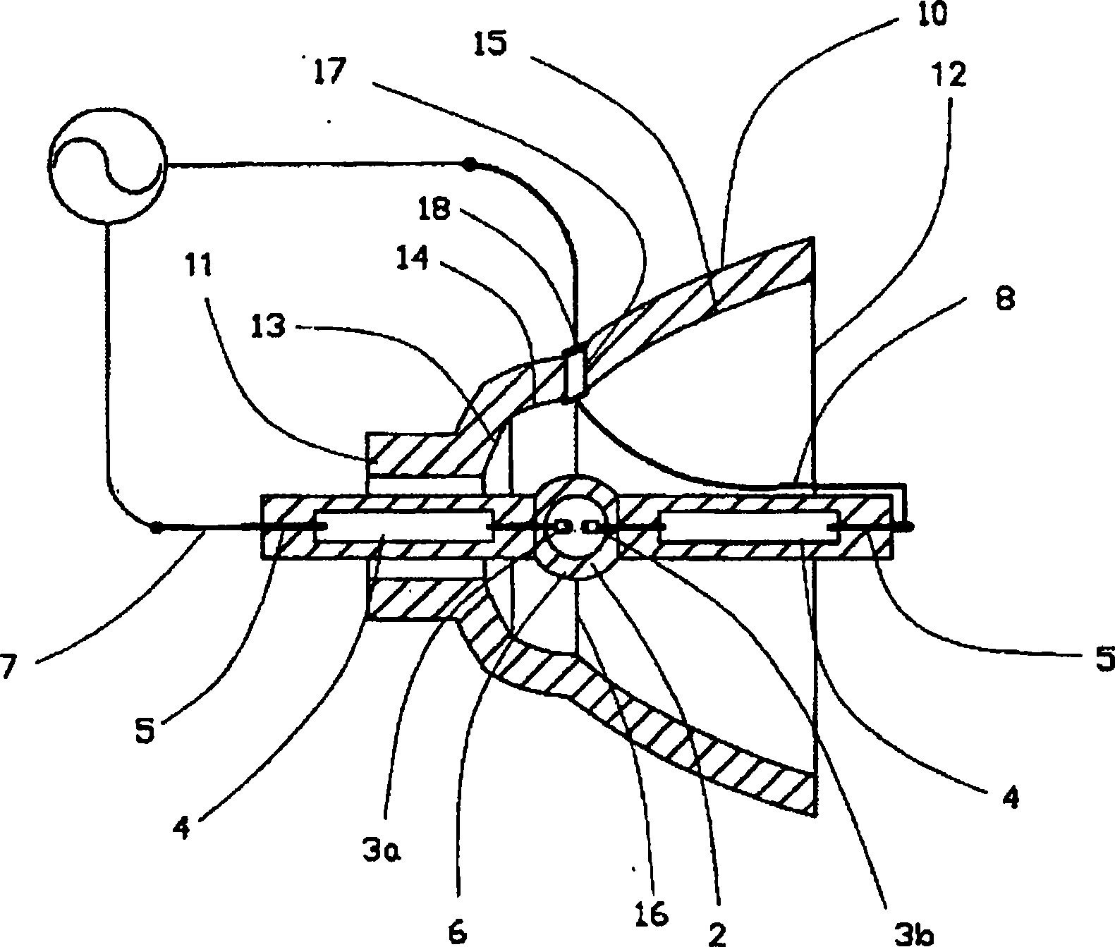
[0033] figure 1 Shows the first embodiment of the present invention. figure 1It is a light source device 1 of the present invention, and the light source device 1 is composed of a discharge lamp 2 and a reflector 10 provided to surround the discharge lamp 2 . In this discharge lamp 2, an electrode 3a and an electrode 3b are provided facing each other, and the electrodes 3a and 3b are respectively connected to a metal foil 4, and an external lead 5 is connected to the other end of the metal foil 4. As shown in FIG. The electrodes 3 a and 3 b are provided inside the bulb part 6 , and mercury, an inert gas, and a trace amount of halogen are sealed inside the bulb part 6 and sealed with the metal foil 4 . In addition, one side of the external lead 5 is connected to the power supply line 7 , and the other side is connected to the high-voltage side power supply line 8 . In addition, the reflector 10 provided around the discharge lamp 2 has a hole 11 for holding the discharge lam...

Embodiment 2

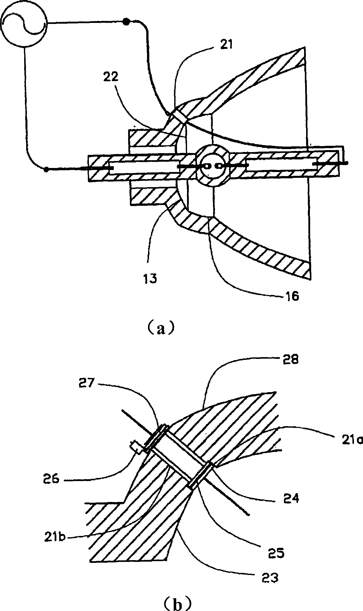
[0037] figure 2 Shows the second embodiment of the present invention. figure 2 In this case, the position where the hole is provided is different from the position where the hole 17 is provided as shown in the first embodiment. The hole portion 21 in the second embodiment is provided on the boundary portion 22 between the central reflective surface 16 and the hole-side reflective surface 13 . also, figure 2 -b) shows an enlarged view of the hole portion 21 . The hole portion 21 is composed of a counterbore 21a with a large diameter and a through hole 21b with a small diameter. As the structure of the outlet 18, for example, a flanged metal cylindrical tube 24 is passed through a hole provided in the buffer member 25 to be inserted into the hole 21, and a metal member is passed through on the back side 28 of the reflection surface 23. 26, and then pass through the hole of the gasket 27, and then use a special clamp to press the end of the metal cylindrical tube with flan...

Embodiment 3

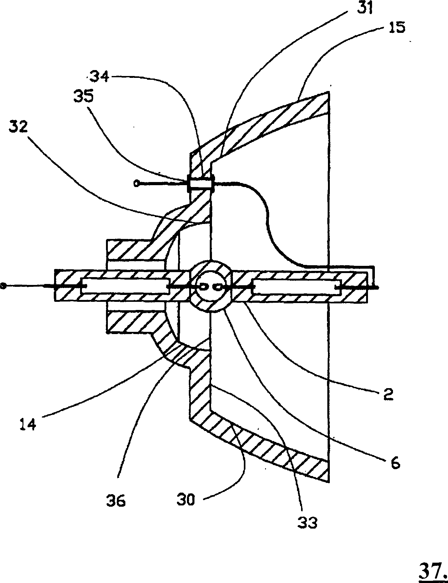
[0041] Figure 4 shows the third embodiment. The reflecting mirror 40 in this embodiment is provided with a boundary portion 43 between the central reflecting surface 14 and the opening-side reflecting surface 15 near the center of the bulb portion 6 of the discharge lamp 2 provided in the reflecting mirror 40 . Cooling air blowing holes 41 are provided on the boundary portion 43 . The cooling air blowing hole 41 is provided on the top side of the bulb with the highest temperature when the discharge lamp 2 is turned on. In addition, in this embodiment, the second cooling air blowing hole 42 is formed on the boundary portion 44 between the central reflection surface 14 and the hole-side reflection surface 13 . According to this configuration, when the discharge lamp 2 is turned on, the top of the bulb with the highest temperature can be cooled intensively, and by adjusting the temperature distribution of the entire discharge lamp 2, a long-life light source device can be prov...


PUM


Abstract

The problem which will be settled by the present invention is to provide a light source device, in the miniature light source device, it catches the light emitted from the electric discharging lamp at the scope as wide as possible, and it can effectively utilize the light emitted from the electric discharging lamp. The light source device of the present invention is composed of an electric discharging lamp and a concave reflecting mirror, the electric discharging lamp includes a pair of opposite electrodes, a bulb part which folds the electrodes internally, the hydrargyrum with density above 0.15mg / mm3 which is sealed in the bulb part and the inert gas, and the concave reflecting mirror is set that it surrounds the electric discharging lamp, the light source device comprises the followingcharacters: the concave reflecting mirror is composed by connecting the spherical mirror and ellipse or parabolic reflecting mirror, and the connecting boundary part of the two reflecting mirrors is arranged with hole part.

Description

technical field [0001] The invention relates to a light source device composed of a high-pressure discharge lamp and a concave reflector. In particular, it relates to a light source device used in a projector device such as a liquid crystal display device using an ultra-high pressure mercury lamp as a light source or a DLP (digital light processor) using a DMD (digital mirror device). 0.15mg / mm 3 Above the mercury, the mercury vapor pressure when it is lit reaches an ultra-high pressure. Background technique [0002] In recent years, projection-type display devices typified by liquid crystal projectors have been widely used for image transmission and the like. In particular, there has been a recent demand for small projectors that are easy to carry, and various developments have been made. Along with the miniaturization of such devices, the light source device itself installed in the projection display device also needs to be miniaturized. On the other hand, in the use o...

Claims


Application Information

Patent Timeline
Patent Type & Authority Patents(China)
IPC IPC(8): F21V7/09H01J61/12F21Y101/00
Inventor 中山胜之
Owner USHIO DENKI KK
Why Eureka
Try Eureka