

Heat exchange tube and evaporator
A technology of heat exchange tubes and evaporators, applied in heat exchange equipment, evaporators/condensers, indirect heat exchangers, etc., can solve problems such as the impact of fuel consumption, and achieve the effect of improving liquid retention performance and comfort
Inactive Publication Date: 2007-12-05
KEIHIN THERMAL TECH CORP
View PDF1 Cites 21 Cited by
- Summary
- Abstract
- Description
- Claims
- Application Information
AI Technical Summary
Problems solved by technology
However, in the evaporator described in the above publication, in order to reduce the temperature difference of the air blown into the cabin when the compressor is turned on and off, the set temperature on the high temperature side (t2) is lowered and the set temperature on the low temperature side (t1) is lowered. It is a simple method of temperature difference from the set temperature (t2) on the high temperature side, but at this time, the compressor is frequently turned on and off, which may have a bad influence on the fuel consumption of the vehicle
Method used
View moreImage
Smart ImageViewing Examples

Examples
Embodiment 1
[0094] Consider the evaporator 20 using the heat exchange tube 34 of the structure shown in FIG. for 4.
Embodiment 2
[0096] Consider the evaporator using the heat exchange tube 34A of the structure shown in FIG. Quantity is 4 pcs.
Embodiment 3
[0098] Consider the evaporator using the heat exchange tube 34B of the structure shown in FIG. Quantity is 4 pcs.
Login to View More PUM
 Abstract
An evaporator includes a plurality of flat heat exchange tubes extending in a vertical direction and arranged at intervals along a left-right direction with a width direction thereof coinciding with a front-rear direction. The heat exchange tube has a plurality of refrigerant channels arranged along the width direction. The evaporator satisfies a relation 0.558<=A<=1.235, where A is a value in pieces / mm obtained by dividing the number N of the refrigerant channels of the heat exchange tube by a width W of the heat exchange tube as measured in the front-rear direction. Also, the evaporator satisfies a relation 0.35<=Dh<=1.0, where Dh is an equivalent diameter in mm of the heat exchange tube. This evaporator can reduce the temperature difference between air discharged into a compartment when a compressor is turned ON and that when the compressor is turned OFF.
Description
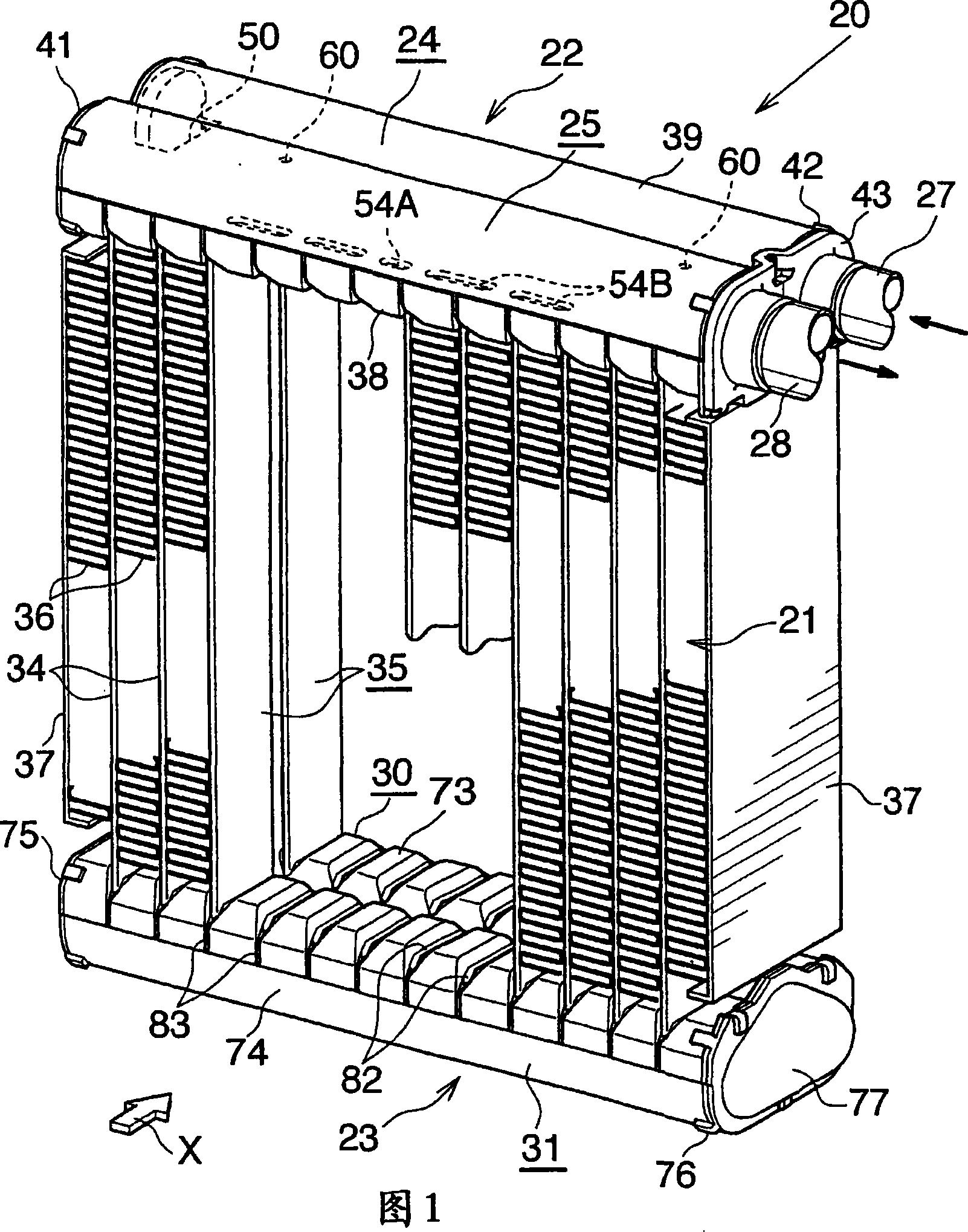
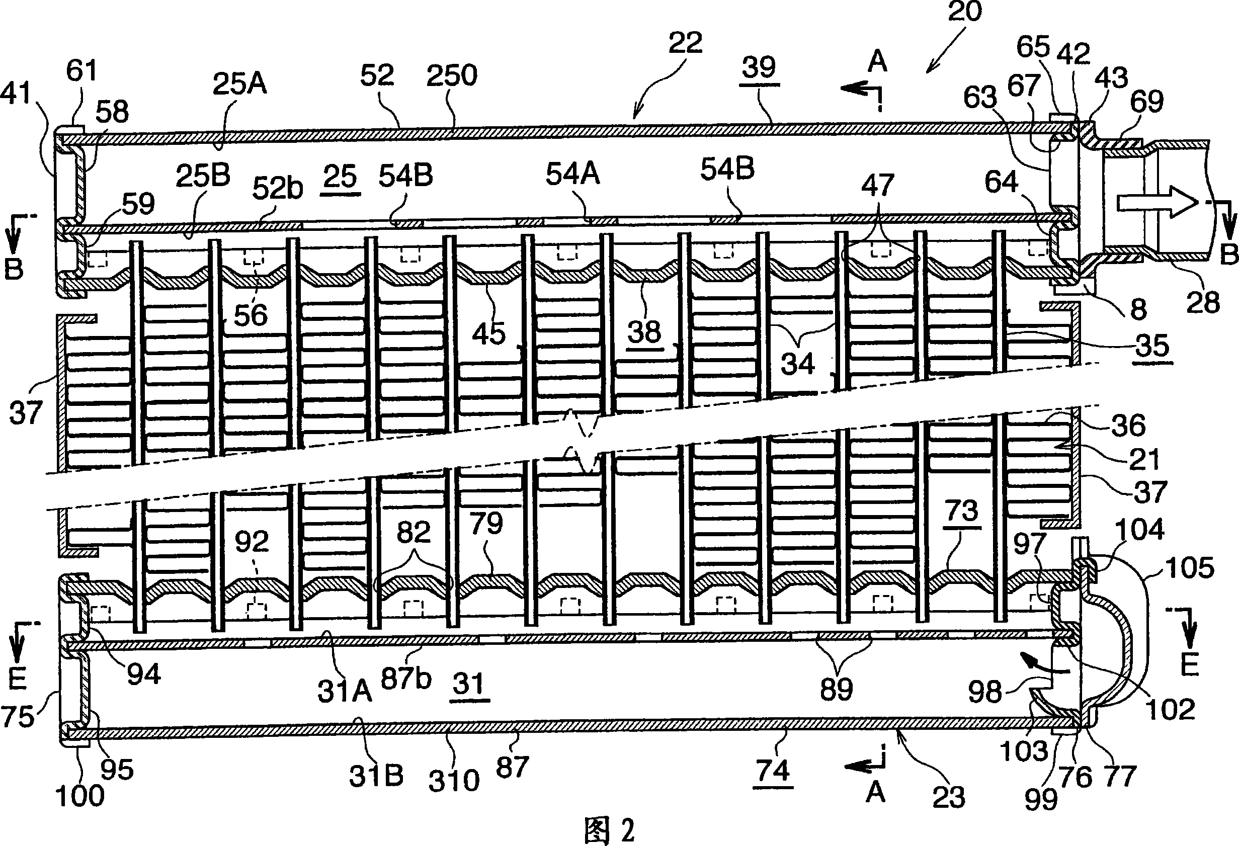
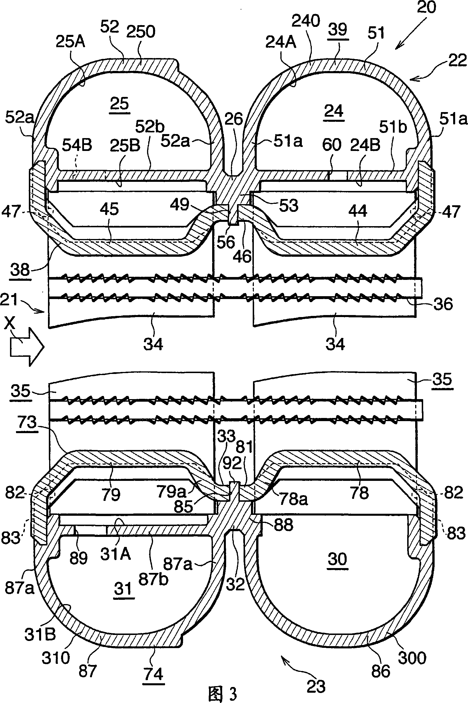
technical field [0001] The present invention relates to a heat exchange tube and an evaporator. More specifically, the present invention relates to a heat exchange tube and an evaporator suitable for use in an evaporator of a vehicle air conditioner which is a refrigeration cycle mounted on a vehicle. Background technique [0002] In this specification and claims, the downstream side of the air flowing through the ventilation gap between the adjacent heat exchange tubes (direction indicated by arrow X in Fig. 1) is taken as the front, and the opposite side is taken as the rear, and respectively shown in Fig. Up and down, left and right in 2 are up and down, left and right. Also in this specification, the term "aluminum" includes aluminum alloys other than pure aluminum. [0003] Conventionally, as evaporators used in vehicle air conditioners, so-called laminated evaporators have been widely used. In laminated evaporators, a pair of plate-shaped plates face each other and we...
Claims
Login to View More Application Information
Patent Timeline
 Patent Type & AuthorityApplications(China)
IPC IPC(8): F28F1/02F25B39/02
CPCF25B39/022F25B2500/01F28D1/05391F28D2021/0085F28F1/022F28F1/126F28F1/40F28F3/048F28F9/0204F28F9/0246F28F2220/00
Inventor东山直久森大辅渡边纯孝
OwnerKEIHIN THERMAL TECH CORP