Resonant tuning fork structure having strong self-coupling performance

A self-coupling and tuning fork technology, applied in the field of core sensitive components, can solve problems such as vibration amplitude modulation, unfavorable signal processing of resonant tuning forks, and affecting the vibration effect of tuning forks, so as to strengthen vibration coupling, reduce equivalent stiffness, and increase equivalent stiffness Effect

Inactive Publication Date: 2011-08-24
BEIHANG UNIV
View PDF0 Cites 0 Cited by
  • Summary
  • Abstract
  • Description
  • Claims
  • Application Information

AI Technical Summary

Problems solved by technology

However, since the differential mode resonance frequency of the resonant tuning fork is very close to the common mode resonance frequency, the two resonance modes will form a vibration coupling phenomenon in the real device, resulting in a vibration amplitude modulation phenomenon, that is, the beat frequency
This phenomenon is extremely unfavorable for the start-up of the resonant tuning fork and the signal processing of the subsequent circuit.
For common-mode vibration, not only will it form a strong vibration coupling with the surrounding structure, but also when various external interference factors act on the two tuning forks at the same time, it will easily change the resonance state of the tuning fork, seriously affecting the vibration effect of the tuning fork
And because the root fixation cannot achieve a completely rigid connection, and the differential mode vibration has little dependence on the root fixation method, so the equivalent stiffness of the common mode vibration will be slightly smaller than the differential mode vibration, making the differential mode vibration easier to vibrate

Method used


Image

  • Resonant tuning fork structure having strong self-coupling performance
  • Resonant tuning fork structure having strong self-coupling performance
  • Resonant tuning fork structure having strong self-coupling performance

Examples


Embodiment Construction

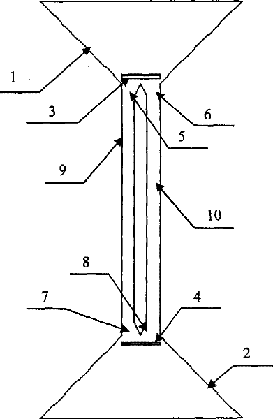
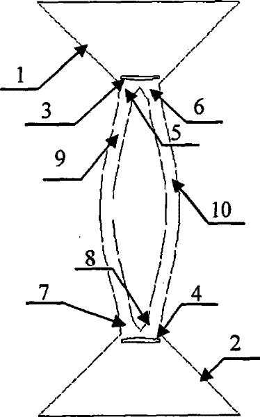
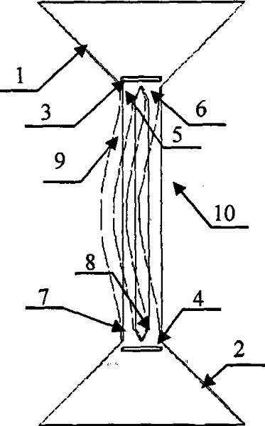
[0011] Such as figure 1 As shown, the present invention includes a symmetrical upper trapezoidal base 1 and a lower trapezoidal base 2 that are used for tuning forks to be fixedly connected with the surrounding two triangles. The upper vibration isolation hole 3 in the upper trapezoidal base 1 and the lower The lower vibration isolation hole 4 in the trapezoidal base 2, the upper vibration isolation hole 3 and the lower vibration isolation hole 4 are symmetrical; the left and right two symmetrical upper resonant beam support bases 5, 6 are rigidly connected with the short side of the trapezoidal base 1, The left and right two symmetrical lower resonant beam support bases 7, 8 are rigidly connected to the short side of the trapezoidal base 2, and the left and right symmetrical resonant beams 9, 10 are located in the middle of the entire tuning fork structure, forming a resonant tuning fork, and passing through the left and right two The upper resonant beam support base 5, 6 and...


PUM


Abstract

The invention relates to a resonance tuning fork structure which has the strong self-coupling characteristic, including a symmetrical upper trapezoidal base (1) and a lower trapezoidal base (2) of the two triangle relative laying aside which is used in fix-connecting the circumambience with the tuning fork, two symmetrical upper vibration isolation hole (3) on the upper trapezoidal base (1) and the lower vibration isolation hole (4) on the lower trapezoidal base (2), two left-right symmetrical upper resonance girder support bases (5, 6) which are located at the lower extremity of the upper vibration isolation hole (3), two left-right symmetrical lower resonance girder support bases (7, 8) which are located at the superior extremity of the lower vibration isolation hole (4), two left-right symmetrical resonance girders (9, 10) which are located on the middle of the entire tuning fork structure to compose the resonance tuning fork, and are supported between the upper trapezoidal base (1) and the lower trapezoidal base (2) through the two left-right upper resonance girder support bases (5, 6) and the two left-right lower resonant girder support bases (7, 8). The invention increases the equivalent stiffness of the tuning fork syntype vibration effectively, so that the different mold resonance frequency of the resonant tuning fork is smaller than the syntype resonance frequency, and the resonant tuning fork work is more stabler and reliable.

Description

technical field [0001] The invention relates to a resonant tuning fork structure, which is used in the field of force detection sensors including silicon microresonant accelerometers, quartz resonant tuning fork accelerometers, silicon micromechanical gyroscopes, etc., and becomes the core sensitive element of such sensors. Background technique [0002] The tuning fork structure is generally used in the field of measurement of mechanical quantities, and belongs to the secondary sensitive element in the sensor. Typical sensors made of resonant tuning forks include resonant accelerometers, resonant mechanical gyroscopes, and resonant air pressure sensors. These sensors convert the measured contact force into an elastic deformation form through a specific mechanism, and then transmit this contact force to the axial direction of the resonant tuning fork through the clamping mechanism to generate an axial force. By changing the axial force of the resonant tuning fork, the equiva...

Claims


Application Information

Patent Timeline
Patent Type & Authority Patents(China)
IPC IPC(8): H03H9/21H03H9/02G01D5/00
Inventor 樊尚春庄海涵郭占社
Owner BEIHANG UNIV
Why Eureka
Try Eureka