
Method for welding FPC plate with PCB plate and its dedicated clamp

A technology of PCB board and welding method, which is applied in the field of welding of FPC board and PCB board and its special fixture, can solve the problems of affecting product quality, high welding cost, poor product reliability, etc., and achieve good consistency of welding temperature curve, welding High reliability and small product temperature difference

Active Publication Date: 2007-12-05
SHENZHEN NEOPHOTONICS TECH
View PDF0 Cites 50 Cited by
  • Summary
  • Abstract
  • Description
  • Claims
  • Application Information

AI Technical Summary

Problems solved by technology

[0010] 1. The working time must be invested separately, which increases the product production turnover cycle, and cannot form a flow operation with the SMT process;
[0011] 2. A single unit can only weld one FPC board at a time. When switching between different products, it is necessary to replace the fixtures, indenters and other devices of the product, and to do a series of debugging, inspection and other steps before welding can be performed. In this way, in this During the process, the pulse heating reflow soldering machine must be shut down for more than half an hour, resulting in extremely low production efficiency;
[0012] 3. The cost of each pulse heating reflow welding machine is more than tens of thousands of yuan, resulting in higher welding costs;
[0013] 4. When welding different single products of the same batch, the temperature curve has a deviation (the error is generally 5 degrees to 10 degrees), resulting in poor product reliability;
[0014] 5. The hot electrode used in the pulse heating reflow welding machine also has a periodic state in daily work, which cannot achieve high consistency, so it will also affect product quality;

Method used


Image

  • Method for welding FPC plate with PCB plate and its dedicated clamp
  • Method for welding FPC plate with PCB plate and its dedicated clamp
  • Method for welding FPC plate with PCB plate and its dedicated clamp

Examples


Embodiment Construction

[0031] The preferred embodiment of the present invention will be described in detail below in conjunction with the accompanying drawings.

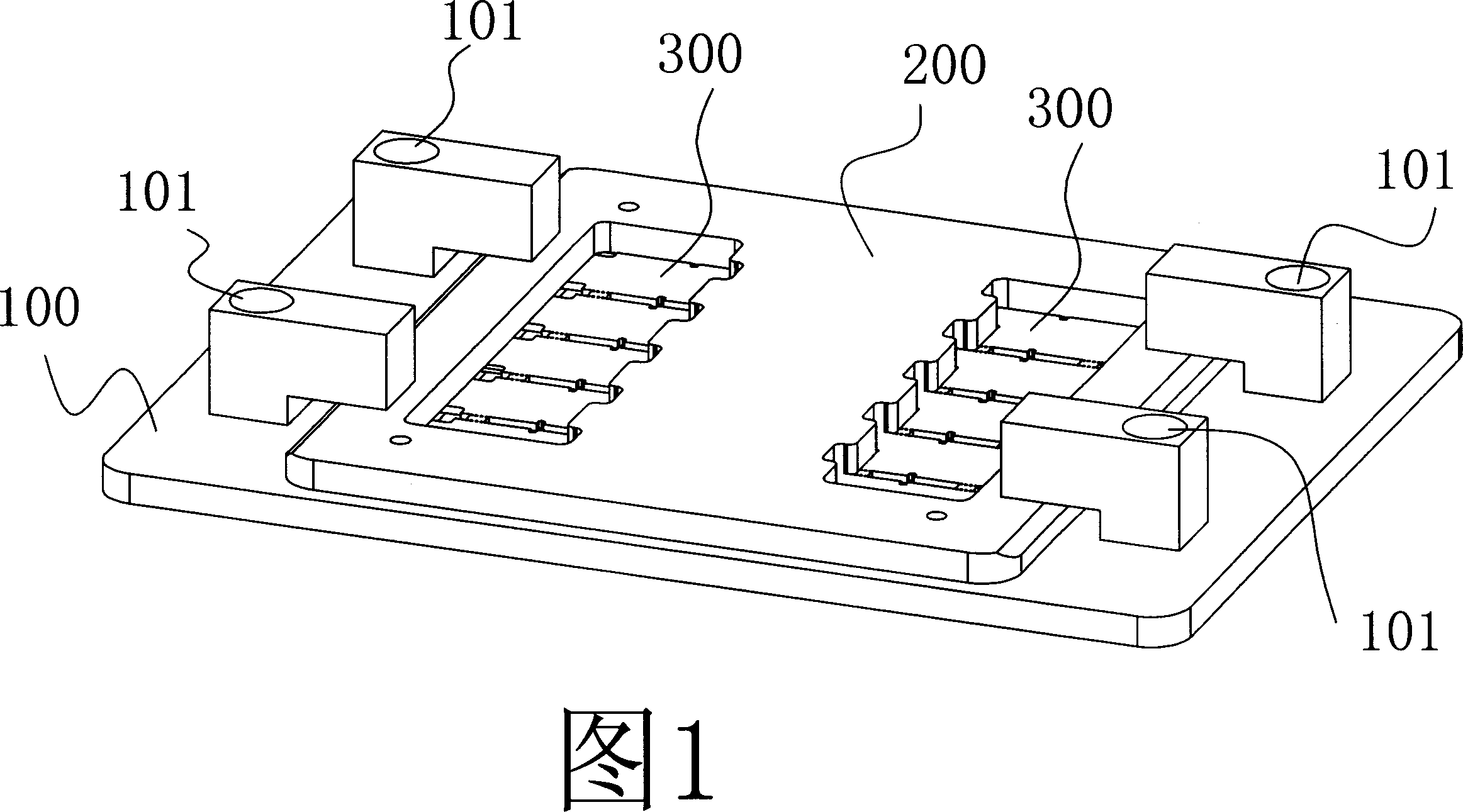
[0032] As shown in FIG. 1 , the special fixture includes: a lower template 100 and an upper template 200 , and a PCB board 300 is sandwiched between the two templates.

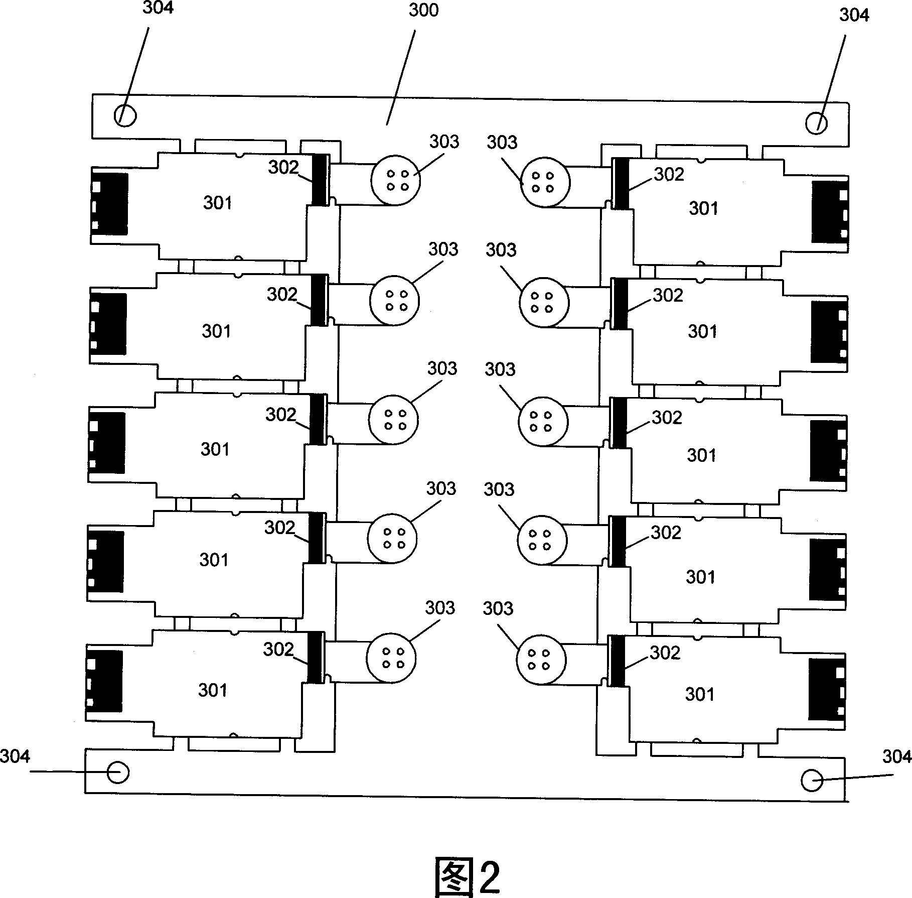
[0033] As shown in Figure 2, the PCB board 300 is a large piece formed by more than one small PCB board 301. There must be enough space for mounting the FPC board 303 on the PCB board 300, and each PCB board 301 can be welded at least A piece of FPC board 303 and four corners of PCB board 300 are symmetrically provided with positioning holes 304 . In this embodiment, 10 small PCB boards 301 are joined together to form a large PCB board 300, and the edge of each small PCB board 301 has a pad position 302 connected with the FPC board 303, and the pad position 302 can be located on the PCB the middle of the small board 301 .

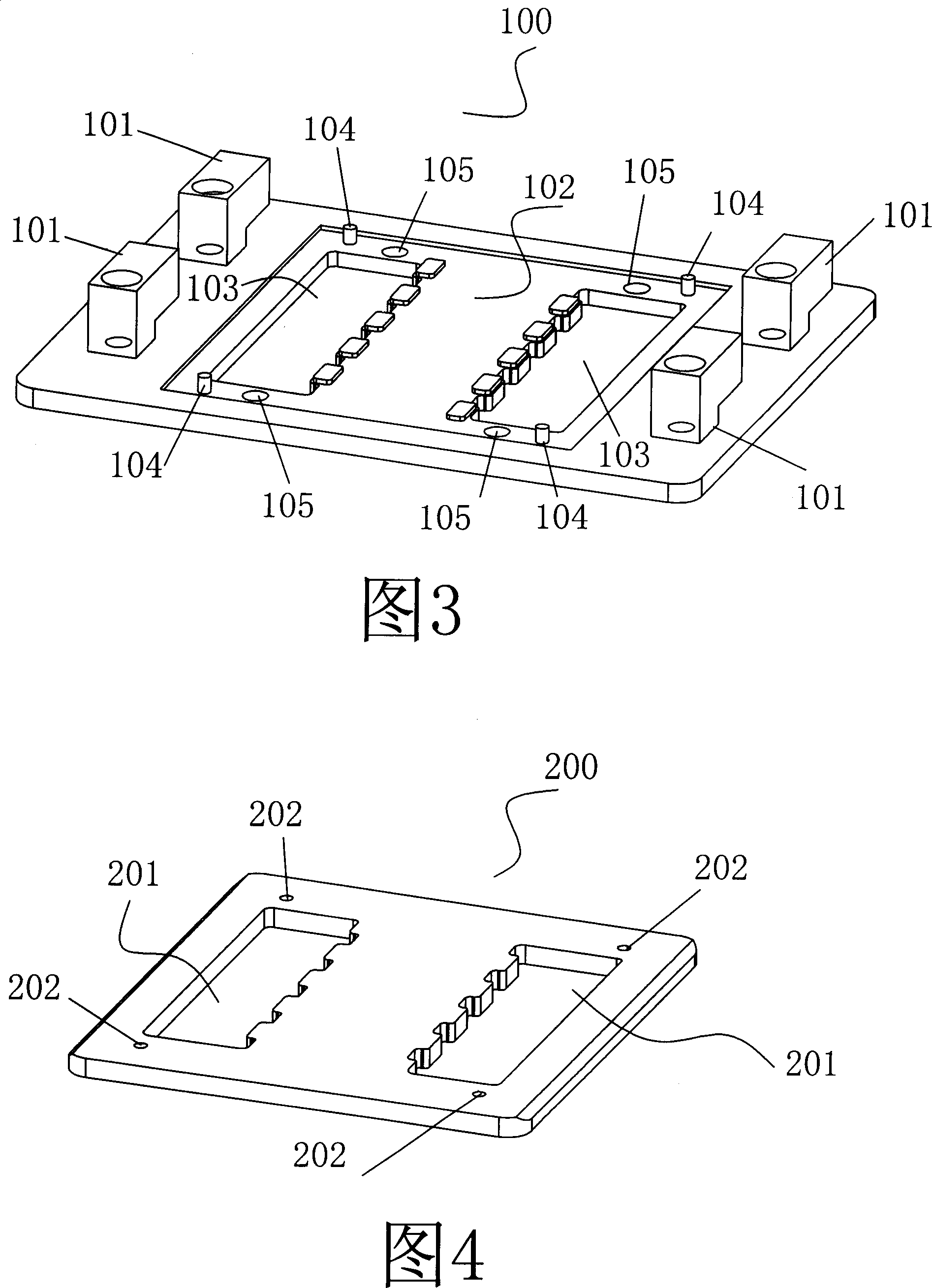
[0034] As shown in Figure 3, the lower formwork...


PUM


Abstract

The present invention offers a method of welding FPC board and PCB board, and the special fixture for this method which includes an upper-template and an under-template. The method includes the following steps: the first step, printing solder paste onto a big-piece PCB board composed of several small-piece PCB boards; the second step, using SMT to compose components onto the PCB board; the third step, fixing the PCB board in the slot of under-template of the fixture for locating; the fourth step, aligning the solder pad zones of FPC board and PCB board; the fifth step, covering the upper-template of the fixture to the upper-surface of the PCB board, and the overlapped area of solder-pad zone is 50%-80%, the under-surface of the upper-template should must maintain horizontal, rotating the block button on the under-template to fasten the upper-template; the sixth step, sending the fastened fixture into enclosed reflow oven for refluxing weld; the seventh step, taking off the template, checking the welding state between FPC board and PCB board. As the said welding method is less in steps and simple in its special fixture, the productive efficiency is high, and the cost is low.

Description

technical field [0001] The invention relates to a welding method of an FPC board and a PCB board and a special fixture thereof. Background technique [0002] FPC board or Flexible Printed Circuit Board (Flexible Printed Circuit Board referred to as FPC) is a printed circuit board made of flexible insulating substrates, which has many advantages that PCB boards - rigid printed circuit boards do not have. For example, it can be freely bent, wound, and folded, and can be arranged arbitrarily according to the requirements of the spatial layout, and can be moved and stretched arbitrarily in three-dimensional space, so as to achieve the integration of component assembly and wire connection. The use of FPC can greatly reduce the volume of electronic products, which is suitable for the development of electronic products in the direction of high density, miniaturization and high reliability. Therefore, FPC has been widely used in aerospace, military, mobile communications, laptop co...

Claims


Application Information

Patent Timeline
IPC IPC(8): H05K3/36H05K3/34
Inventor 何仲明詹海涛谢斌唐宗敏
Owner SHENZHEN NEOPHOTONICS TECH
Learn More