Instant opening-closing apparatus fastener device
A locking device and sleeve technology, which is applied in the direction of mechanical equipment, fixing devices, etc., can solve the problems of a lot of time spent on installation or removal, manpower, voids, scratches, resource consumption, etc., to save time and manpower, and lock operation Convenience and the effect of maintaining cleanliness
- Summary
- Abstract
- Description
- Claims
- Application Information
AI Technical Summary
Problems solved by technology
Method used
Image
Examples
Embodiment 1
[0037] The specific structure of the instant opening and closing device locking device
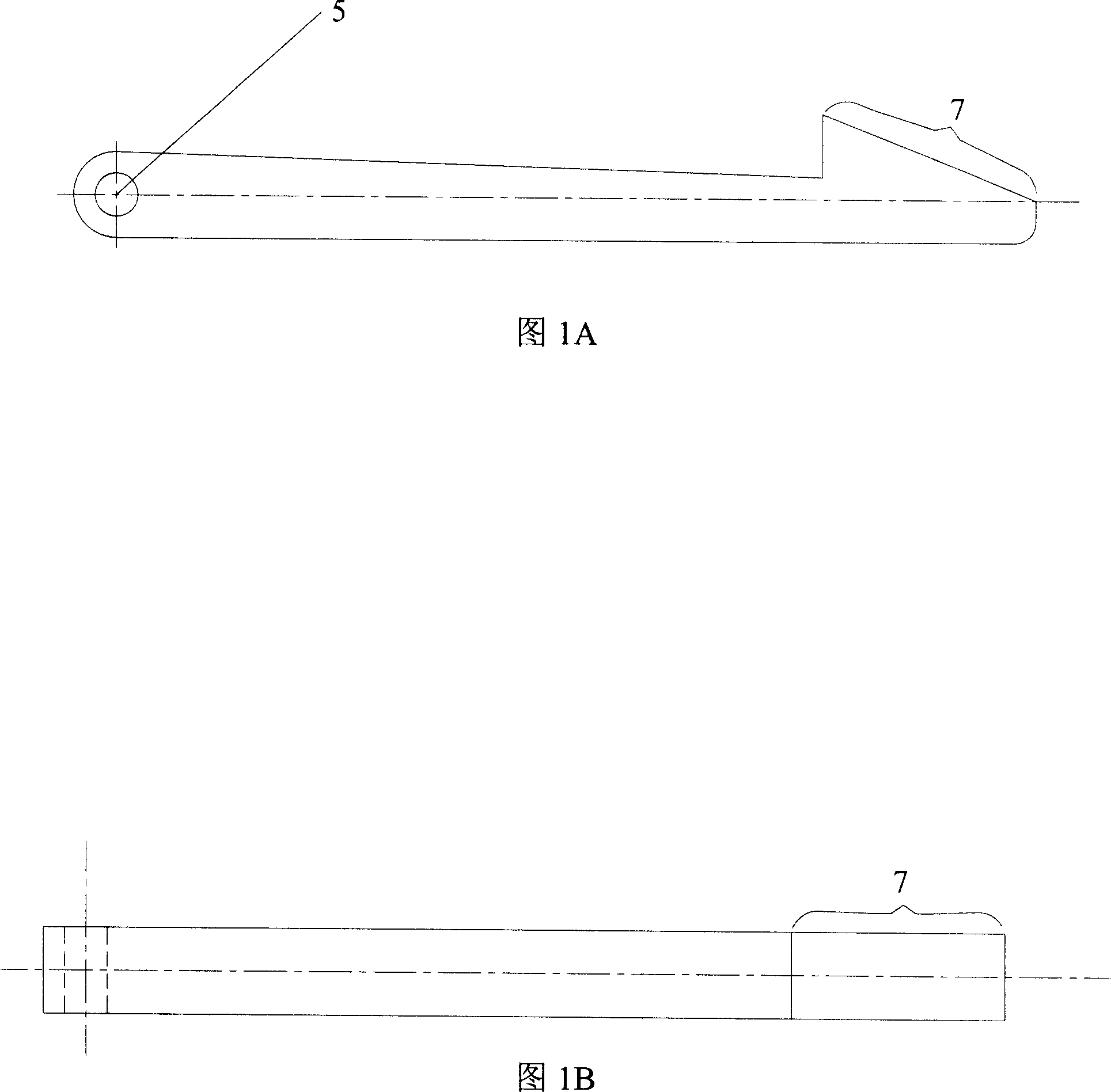
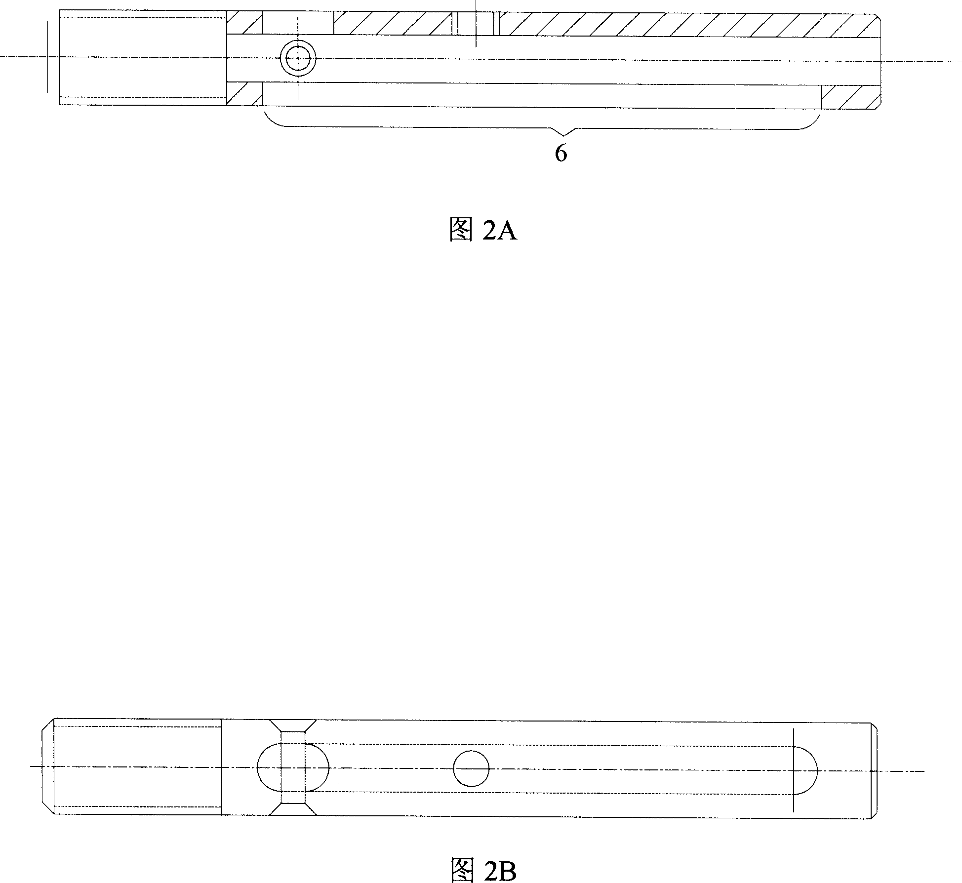
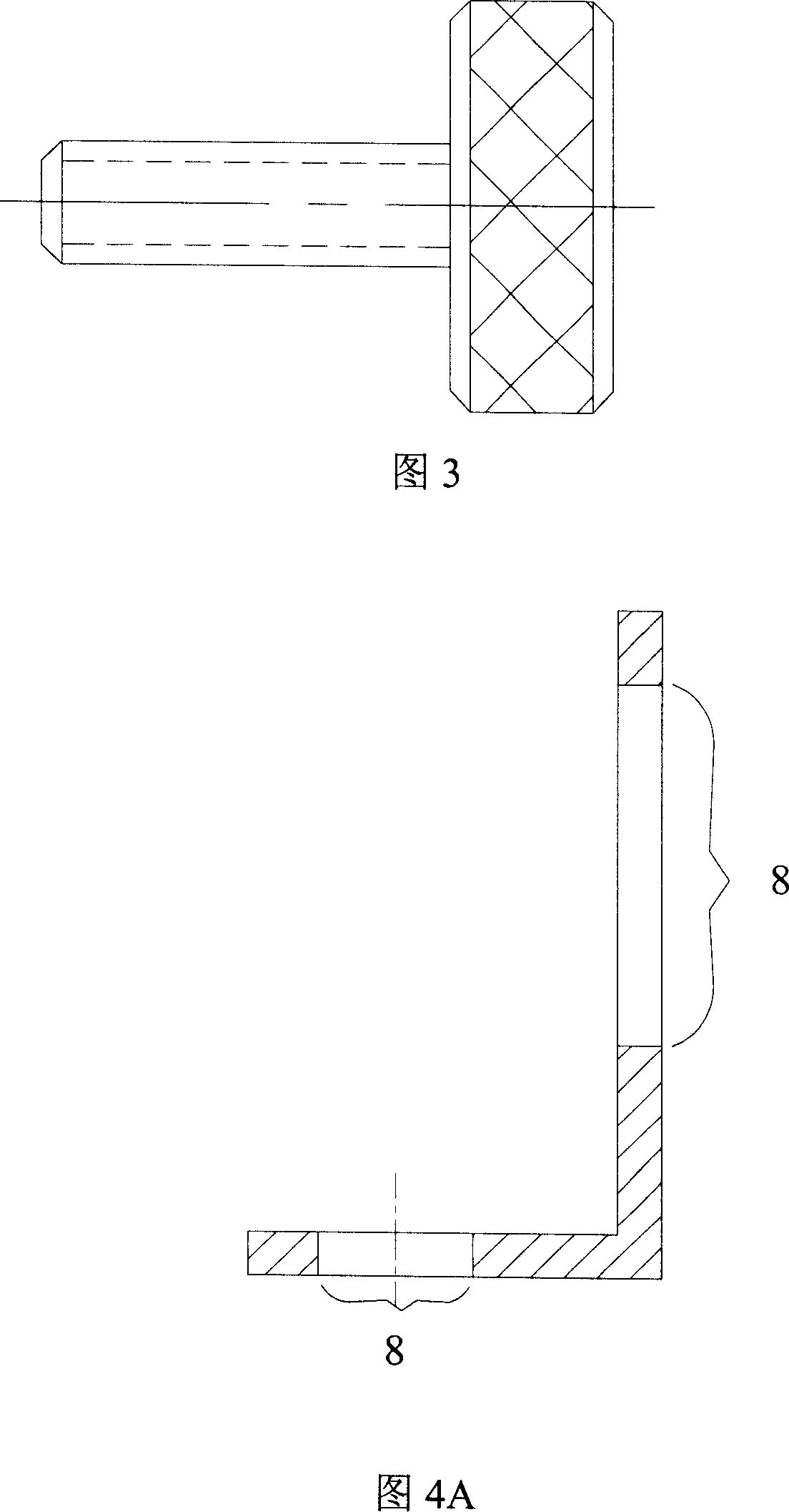
[0038] This embodiment provides a specific example of a locking device for an instant opening and closing device, which includes the following main components: a hook 1 , a sleeve 2 , a positioning nut 3 and a right-angle plate 4 .
[0039] Figure 1a and Figure 1b are the front view and the top view of the hook 1 respectively, the number 11 in Figure 1a represents the hook tip outer slope of the hook, and the number 12 is the place where the hook is connected by the pin and the sleeve, that is, the pin hole;
[0040] Fig. 2 a and Fig. 2 b are the front view and the top view of sleeve 2 respectively, and the number 21 in Fig. 2 a represents the groove on the sleeve, and the number 22 represents the nut hole that is compatible with positioning nut 3;
[0041] Fig. 3 is the front view of positioning nut 3, and positioning nut has the screw thread that accords with hole 22;
[0042] Figures 4...
Embodiment 2
[0047] The use process of the instant opening and closing device locking device
[0048]When it is necessary to fix the equipment in the clean room, such as a cart with wheels, the locking device provided in Embodiment 1 is used. The size and length of the sleeve and the hook of the locking device have been designed to be consistent with the floor of the clean room. Existing holes are suitable, and the axle of cart can be used as screw 7 shown in Figure 5.
[0049] Firstly, the locking device of Embodiment 1 is sleeved on the wheel shaft through the right-angle plate 4, that is, on the screw 7, and then the sleeve 2 of the locking device is inserted vertically downward into the hole on the floor of the clean room, because the sleeve 2 The outside of the hook tip of the hook 1 is a slope structure 11. During the insertion process, the part of the hook exposed outside the slot 21 of the sleeve 2 is affected by the force of the slope 11, and retracts into the sleeve 2 until the s...
Embodiment 3
[0052] Another design scheme of the equipment locking device of the present invention
[0053] Please refer to the front view of the locking device in the combined state shown in Figure 8, each component of the locking device provided in this embodiment can refer to the solution of embodiment 1, the difference with respect to embodiment 1 is that the positioning nut 3. Instead of controlling the entry and exit through the threads of the hole 22 of the sleeve 2, but by setting a return spring between the positioning nut 3 and the sleeve 2, the entry and exit of the positioning nut 3 is controlled by pressing and spring reset; correspondingly , the protruding direction of the hook tip of the hook 1 should also be adjusted to the opposite of that of Example 1.
[0054] When using this locking device to fix the equipment, insert the sleeve 2 into the corresponding hole. Due to the action of the inclined surface structure 11 outside the hook tip, the hook 1 rotates around the pin a...
PUM
 Abstract
Description
Claims
Application Information
 - R&D
- Intellectual Property
- Life Sciences
- Materials
- Tech Scout
- Unparalleled Data Quality
- Higher Quality Content
- 60% Fewer Hallucinations
Browse by: Latest US Patents, China's latest patents, Technical Efficacy Thesaurus, Application Domain, Technology Topic, Popular Technical Reports.
© 2025 PatSnap. All rights reserved.Legal|Privacy policy|Modern Slavery Act Transparency Statement|Sitemap|About US| Contact US: help@patsnap.com


