Cleaning device

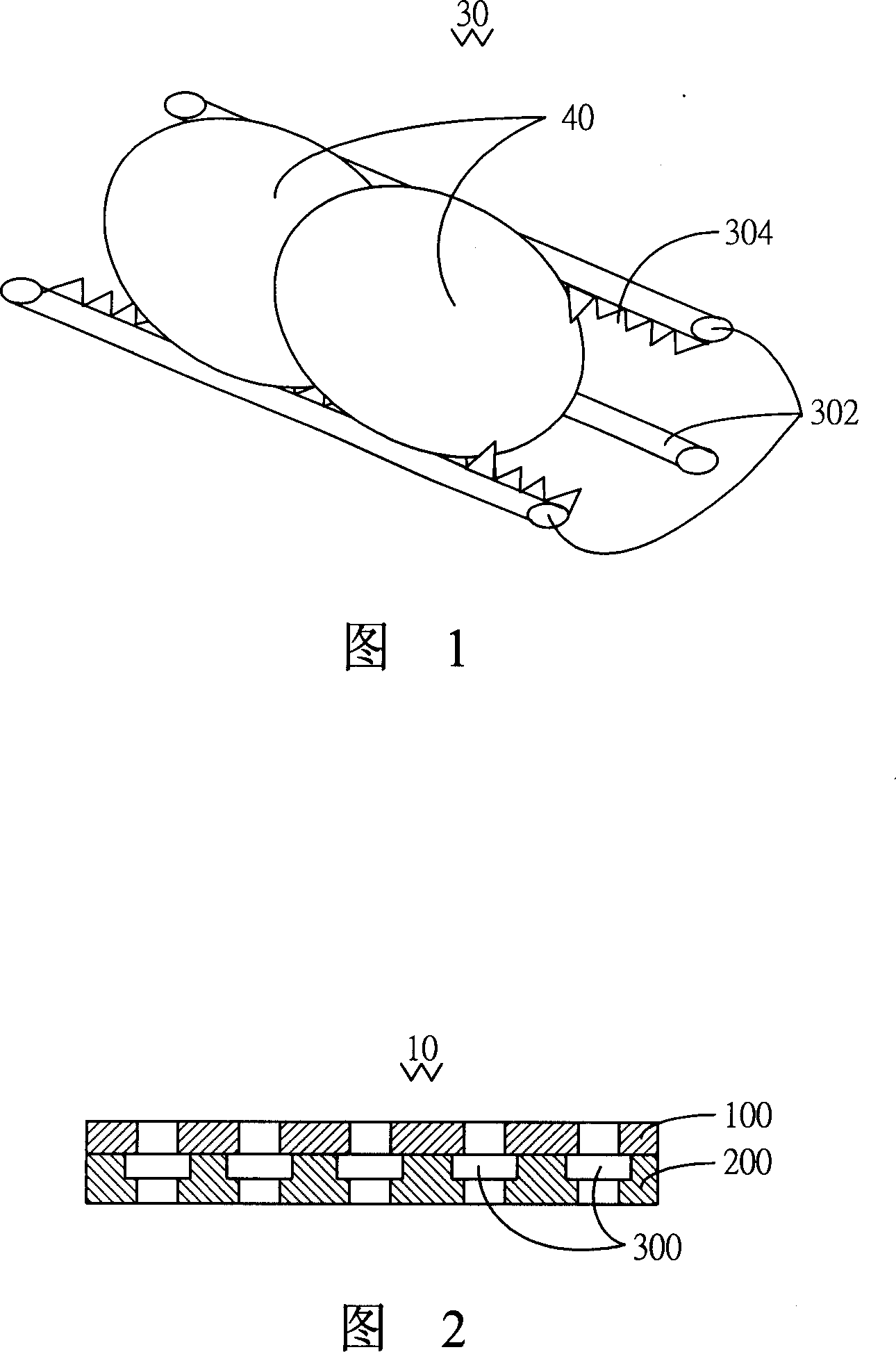
A jig and body technology, applied in cleaning methods and utensils, manufacturing tools, cleaning flexible objects, etc., can solve the problems that the optical element 40 is not clean, the optical element 40 is not easy to put in, damaged, etc.

Inactive Publication Date: 2007-12-19
HONG FU JIN PRECISION IND (SHENZHEN) CO LTD +1
View PDF0 Cites 7 Cited by
  • Summary
  • Abstract
  • Description
  • Claims
  • Application Information

AI Technical Summary

Problems solved by technology

However, the thickness and depth of the V-groove 304 formed by Teflon will block the water flow, so that the clamped part of the optical element 40 will not be cleaned cleanly. Furthermore, during the cleaning process, if the clamped optical element 40 is too loose, the optical element 40 will be damaged. Component 40 could not withstand the post-ultrasonic vibration and fell off
Or the clamping is too tight, the optical element 40 is difficult to put in and take out, and it is easy to cause damage

Method used


Image

  • Cleaning device
  • Cleaning device
  • Cleaning device

Examples


Embodiment Construction

[0019] The embodiments of the present invention will be further described in detail below in conjunction with the accompanying drawings.

[0020] Referring to FIG. 2 , the first embodiment of the present invention provides a jig 10 , the jig 10 includes a cover 100 and a body 200 . The material of the jig 10 is one of aluminum, aluminum alloy, stainless steel, titanium alloy, copper and heat-resistant engineering plastics, and the jig 10 can be manufactured by using CNC processing technology.

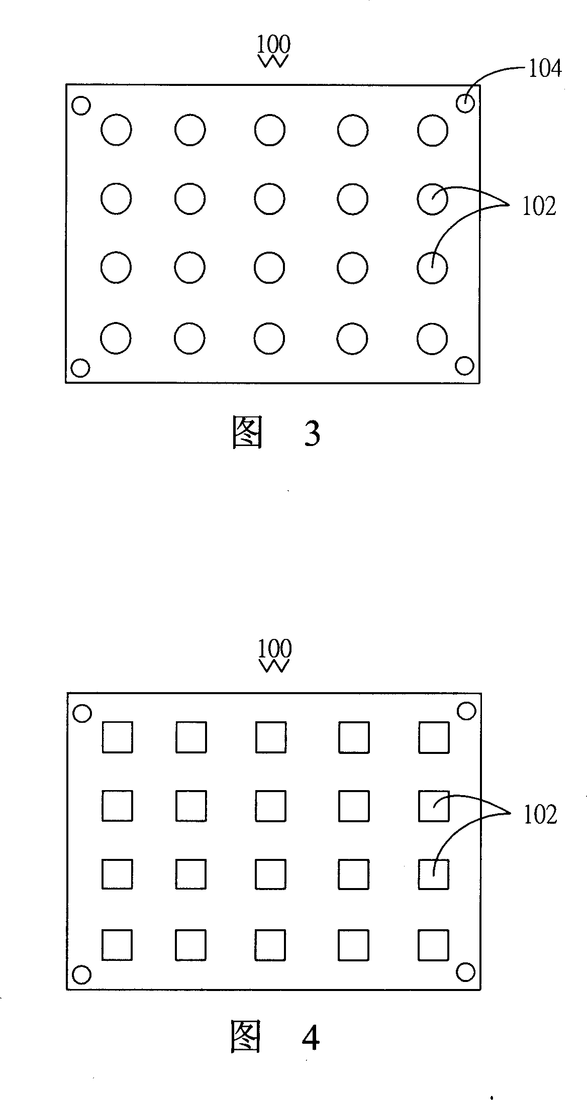
[0021] The cover body 100 defines a plurality of first through holes 102 , and the plurality of first through holes 102 are opened on the cover body 100 at a certain distance. In this embodiment, as shown in FIG. 3 , the plurality of first through holes 102 are circular holes. Certainly, the plurality of first through holes 102 may also be square holes, as shown in FIG. 4 , or other shapes, such as triangular holes, rhombus holes, and the like.

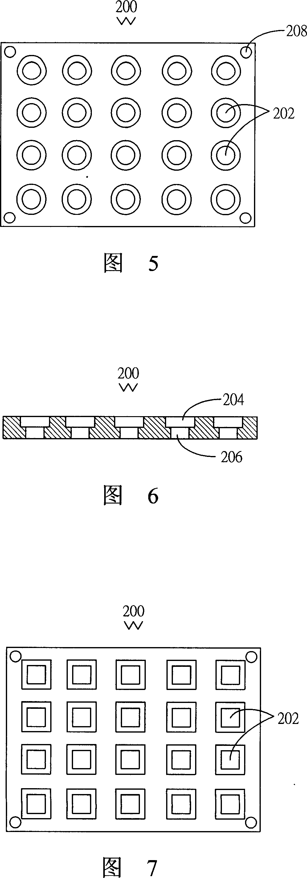
[0022] The body 200 defines a pluralit...


PUM


Abstract

The optical element cleaning device includes one cover with one first through hole, and one body with one second through hole corresponding to the first one in the cover, with the second through hole being communicated with two opening. The cover is matched to the body to form one optical element holding and limiting space, in which detergent may flow easily to well contact with the optical element and result in high cleaning effect. After finishing cleaning, the cover is separated from the body so as to take out the cleaned optical element easily.

Description

technical field [0001] The invention relates to a clamping device, in particular to a jig for cleaning optical elements. Background technique [0002] With the development of multimedia technology, imaging equipment such as cameras, digital cameras, and mobile phone camera lenses are becoming more and more popular among consumers. The image quality puts forward higher requirements, that is, it is hoped that the image of the object to be photographed is clear, and the image quality of the object depends to a large extent on the quality of the optical instruments in the camera. [0003] In-camera imaging modules generally include lenses, optical filters and image sensing components, such as Charge Coupled Device (CCD for short), or Complementary Metal-Oxide Semiconductor (CMOS for short). In the process of producing these optical components such as lenses and optical filters, in order to achieve a high degree of cleanliness, these optical components generally need to go throu...

Claims


Application Information

Patent Timeline
Patent Type & Authority Applications(China)
IPC IPC(8): B08B11/02B25B11/00
CPCG02B27/0006B08B3/047B08B3/045
Inventor 董才士李欣和
Owner HONG FU JIN PRECISION IND (SHENZHEN) CO LTD
Why Eureka
Try Eureka