

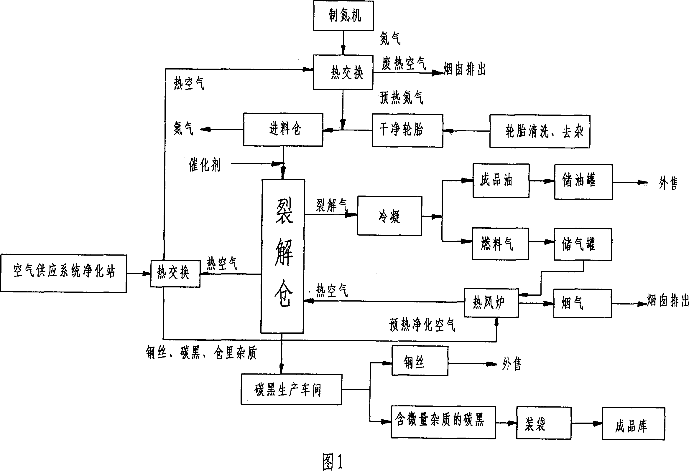
Waste tyre cracking process and apparatus
A technology for waste tires and equipment, applied in the preparation of liquid hydrocarbon mixtures, the petroleum industry, fibrous fillers, etc., can solve the problems of multiple cracking process steps, low catalyst activity, and low production efficiency, and achieve the elimination of cutting processes and optimization Increase ratio, energy saving effect
- Summary
- Abstract
- Description
- Claims
- Application Information
AI Technical Summary
Problems solved by technology
Method used
Image

Examples
Embodiment 1
[0027] Embodiment 1: a. the tire with a weight of 275Kg is cleaned and removed; b. the whole tire and the heated nitrogen are sent into the feed bin together; c. the tire processed through the previous step is sent into the cracking bin, Add 1.375Kg activated clay catalyst at the same time, and heat and crack it for 15 minutes at a temperature of 280°C and a pressure of 0.01 MPa; The steel wire and carbon black are separated and the carbon black is packaged. At the same time, the cracked gas generated after cracking is sent to the condenser for condensation to obtain refined oil and fuel gas. Its generated products are as follows:
[0028] name
Embodiment 2
[0029]Embodiment 2: a. the tire with a weight of 200Kg is cleaned and removed; b. the whole tire and the heated nitrogen are sent into the feeding bin together; c. the tire processed through the previous step is sent into the cracking bin, At the same time, 4Kg of kaolin catalyst was added, and the temperature was 480° C. and the pressure was 0.04 MPa, and it was heated and cracked for 30 minutes;
[0030] d. Send the steel wire and carbon black solid matter produced after cracking into the discharge transition bin, then separate the steel wire and carbon black through magnetic separation and pack the carbon black, and send the cracked gas produced after cracking to into the condenser for condensation to obtain refined oil and fuel gas. Its generated products are as follows:
[0031] name
Embodiment 3
[0032] Embodiment 3: a. the tire with a weight of 300Kg is cleaned and removed; b. the whole tire and the heated nitrogen are sent into the feed bin together; c. the tire processed through the previous step is sent into the cracking bin, Add 1.5Kg kaolin catalyst and 1.5Kg activated clay catalyst at the same time, and heat cracking at a temperature of 450 ° C and a pressure of 0.03 MPa for 20 minutes; d. Send the steel wire and carbon black solid matter produced after cracking into the discharge transition bin Inside, the steel wire and carbon black are separated by magnetic separation and the carbon black is packaged. At the same time, the cracked gas generated after cracking is sent to the condenser for condensation to obtain refined oil and fuel gas. Its generated products are as follows:
[0033] name
PUM
 Abstract
Description
Claims
Application Information