Twist type LED module and LED device

A technology of light-emitting diodes and lamps, applied in the field of device design, can solve the problems of difficult maintenance, difficult design of heat-dissipating lamps, poor heat-dissipation of light-emitting diode modules, etc., and achieves the effect of avoiding burnout and long service life

Inactive Publication Date: 2007-12-19
ANTEYA TECH CORP +1
View PDF0 Cites 25 Cited by
  • Summary
  • Abstract
  • Description
  • Claims
  • Application Information

AI Technical Summary

Problems solved by technology

[0007] The main purpose of the present invention is to provide a screw-in LED module and LED device, hoping to use this design to overcome the disadvantages of poor heat dissipation of the LED module used in the previous light-emitting devices, difficult design of heat-dissipating lamps, and difficult maintenance.

Method used


Image

  • Twist type LED module and LED device
  • Twist type LED module and LED device
  • Twist type LED module and LED device

Examples


Embodiment Construction

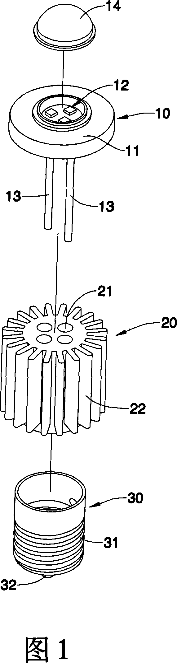
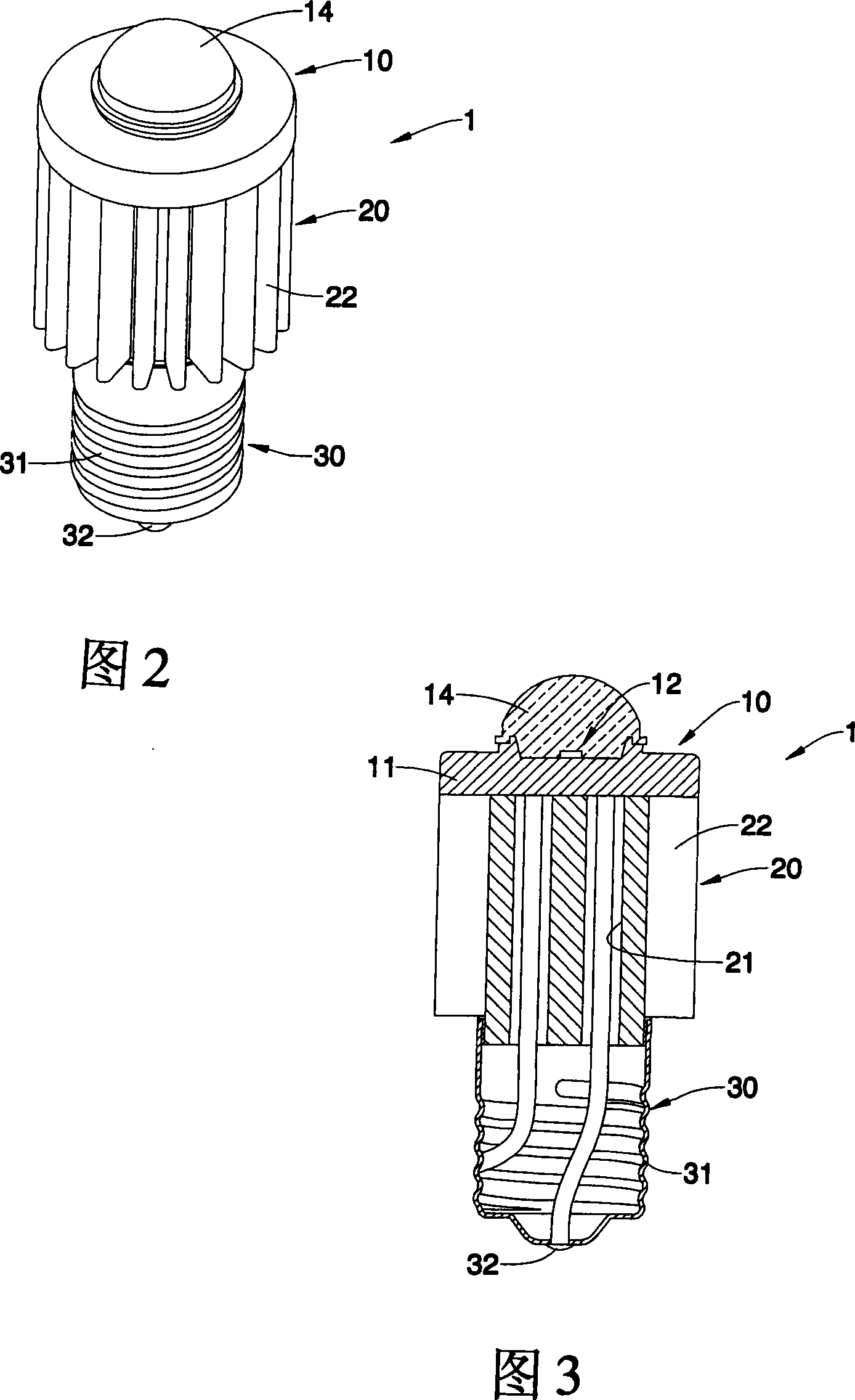
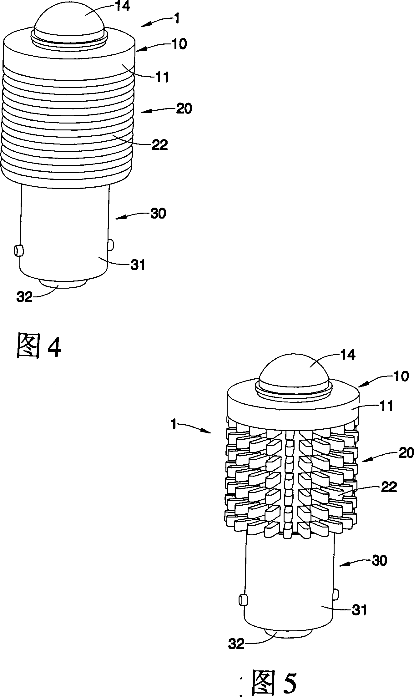
[0071] The present invention includes a screw-in LED module and its composed LED device. The LED device can be light-emitting devices such as light bulbs, lamp tubes or CDs, etc., as shown in Figures 1 to 8 , is to disclose several specific and feasible preferred embodiments of the screw-in LED module of the present invention. It can be seen from the figure that the screw-in LED module (1) mainly includes a high-power LED component (10) , a heat dissipation base (20) and a module connector (30), wherein:

[0072] The high-power LED component (10) comprises an LED metal base (11), a high-power LED chipset (12) arranged on the front face of the LED metal base (11), and a light-transmitting member (14) It is arranged at the front end of the LED metal base (11) and covered on the high-power LED chipset (12).

[0073] The aforementioned high-power LED chipset (12) can be at least one LED chip with the same wavelength, or a combination of at least two LED chips with different wavel...


PUM


Abstract

The present invention relates a screw-plug LED module and LED device. Said screw-plug LED module is characterized by that the rear end of metal base seat of LED component is equipped with a radiating base seat by adopting surface contact mode. Said invention also provides the LED device composed of several screw LED modules, and also provides the concrete structure of said LED device.

Description

Technical field [0001] The invention relates to a light emitting device, in particular to a screw-in LED module and the design of LED light bulbs, lamp tubes or optical discs and other devices including the screw-in LED module. Background technique [0002] Currently known light-emitting devices (such as optical discs) that use light-emitting diode modules, as shown in Figure 13, are mainly arranged on an aluminum circuit board (91) on a base (90) made of a heat-dissipating material. Install a plurality of light-emitting diode modules (92) on the aluminum circuit board (91), and these light-emitting diode modules are respectively fixed on the aluminum circuit board (91) by welding their two metal pins (921). )superior. [0003] However, the above-mentioned light-emitting diode module (92) is applied to light-emitting devices such as optical discs. Although it can provide bright light as illumination or control as a display, etc., the aforementioned light-emitting devices su...

Claims


Application Information

Patent Timeline
Patent Type & Authority Applications(China)
IPC IPC(8): F21V19/00F21V29/00F21V5/08F21Y101/02F21V29/77F21Y115/10
CPCF21V29/2231F21V23/002F21K9/13F21V29/2275F21K9/135F21Y2101/02F21K9/17F21K9/23F21K9/232F21K9/27F21K9/275F21S2/005F21V29/763F21V29/773F21V29/80F21Y2115/10
Inventor 吴定丰苏晋锋林俊宏
Owner ANTEYA TECH CORP
Why Eureka
Try Eureka