
Resin coated metal sheet with excellent electromagnetic wave shielding performance

A metal plate and resin technology, applied in the direction of magnetic/electric field shielding, shielding, metal layered products, etc., to achieve good electromagnetic wave shielding and improve conductivity

Inactive Publication Date: 2007-12-19
KOBE STEEL LTD
View PDF4 Cites 5 Cited by
  • Summary
  • Abstract
  • Description
  • Claims
  • Application Information

AI Technical Summary

Problems solved by technology

Thus, although it is possible to attenuate electromagnetic waves leaking from, for example, gaps between steel plates, there is a problem that the leakage of electromagnetic waves from, for example, air holes and wiring holes cannot be effectively prevented.

Method used


Image

  • Resin coated metal sheet with excellent electromagnetic wave shielding performance
  • Resin coated metal sheet with excellent electromagnetic wave shielding performance
  • Resin coated metal sheet with excellent electromagnetic wave shielding performance

Examples


Embodiment 1

[0106] (Metal plate)

[0107] Using various metal plates (thicknesses are all 0.6 mm) shown below, the surface roughness (Ra) of the tempered roll is changed in the range of 0.6 to 3.2 μm, and the rolling ratio during rolling is 0.3 to By varying within the range of 1.5%, the surface roughness (Ra) of the metal plate is varied within the range of 0.56 to 1.35 μm. Ra of the tempered roll was changed by changing the grain size of the sand grains in the range of #50 to #70, and performing shot peening using a grinding material whose grain size was adjusted.

[0108] In the following description, "%" does not specifically mean mass %. In addition, all plated steel sheets (EG, GI, GA, ZN, ZF) were plated on both sides.

[0109] EG(1): Galvanized steel sheet

[0110] (Single-sided plating adhesion 20g / m 2 , Ra: 0.76μm)

[0111] EG(2): Galvanized steel sheet

[0112] (Single-sided plating adhesion 15g / m 2 , Ra: 0.78μm)

[0113] EG(3): Galvanized steel sheet

[0114] (Single-...


PUM

PropertyMeasurementUnit
glass transition temperatureaaaaaaaaaa
thicknessaaaaaaaaaa
particle sizeaaaaaaaaaa

Abstract

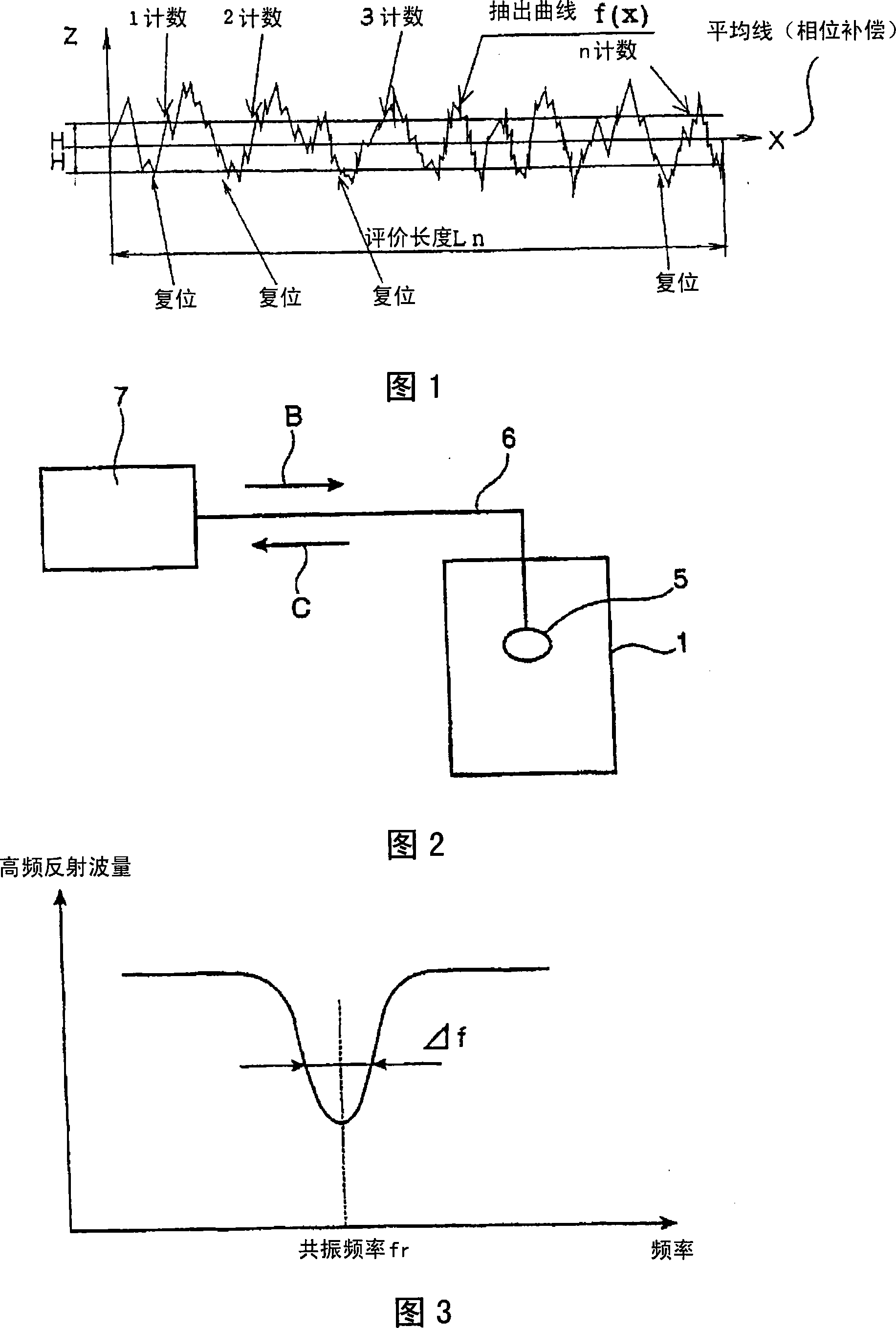
The present invention is a resin-coated metal plate whose surface is covered with a resin film. By improving the electrical conductivity of the resin-coated metal plate, it can exhibit excellent electromagnetic wave shielding properties and preferably can exhibit good characteristics even under light contact. The resin film satisfies the necessary conditions of the following formula (1), that is, PPIt≥70...(1). PPIt represents the number of peak-to-bottom counts when 1 / 2 of the peak count level (2H) is taken as the thickness t (μm) of the resin film in PPI (Peaks PerInch) described in SAE J911-1986.

Description

technical field [0001] The present invention relates to a resin-coated metal sheet excellent in electromagnetic wave shielding properties (conductivity). The resin-coated metal sheet of the present invention is, for example, pressed at a pressure of 10 to 12 g / mm 2 Good electrical conductivity can be exhibited even under light contact (under light pressure) from left to right, so it is suitable, for example, as a constituent material such as a frame of electronic, electrical, and optical equipment (hereinafter sometimes represented by electronic equipment). Background technique [0002] With the improvement of performance and miniaturization of electronic equipment, in order to prevent the electromagnetic waves generated inside the electronic equipment from leaking to the outside, or to prevent the electromagnetic waves intruding from the outside of the electronic equipment from invading the inside, the housings of electronic equipment and the like are required to have Exce...

Claims


Application Information

Patent Timeline
Patent Type & Authority Applications(China)
IPC IPC(8): G12B17/02C22C38/00B32B15/04
CPCC23C2/06H05K9/00C23C26/02C23C28/3225C23C2/26B32B15/08
Inventor 渡濑岳史平野康雄五十岚哲也
Owner KOBE STEEL LTD
Learn More