Dust-proof electric cabinet

An electrical cabinet and dust-proof technology, which is applied in the field of electrical cabinets, can solve the problems of difficult disassembly of the filter screen, dust entering the electrical cabinet, and reduced cooling effect, so as to achieve the effect of improved heat dissipation and ventilation, and good dust removal effect

Inactive Publication Date: 2007-12-19
山东乐航节能科技股份有限公司
View PDF0 Cites 22 Cited by
  • Summary
  • Abstract
  • Description
  • Claims
  • Application Information

AI Technical Summary

Problems solved by technology

[0003] But for the dust-proof method in the prior art, there are many disadvantages: 1. The filter area is small, only filters the narrow area at the air inlet of the fan, and cannot meet the requirements of cooling; A large amount of dust will accumulate in the net, which will prevent the air from entering the cabinet freely, and the cooling effect will be greatly reduced; 3. The filter screen cannot be installed at the air outlet of the electrical cabinet, and dust will enter the electrical cabinet when the machine is shut down; 4. The filter screen with dust accumulated Not easy to disassemble, inconvenient to clean in time

Method used


Image

  • Dust-proof electric cabinet
  • Dust-proof electric cabinet
  • Dust-proof electric cabinet

Examples


Embodiment 1

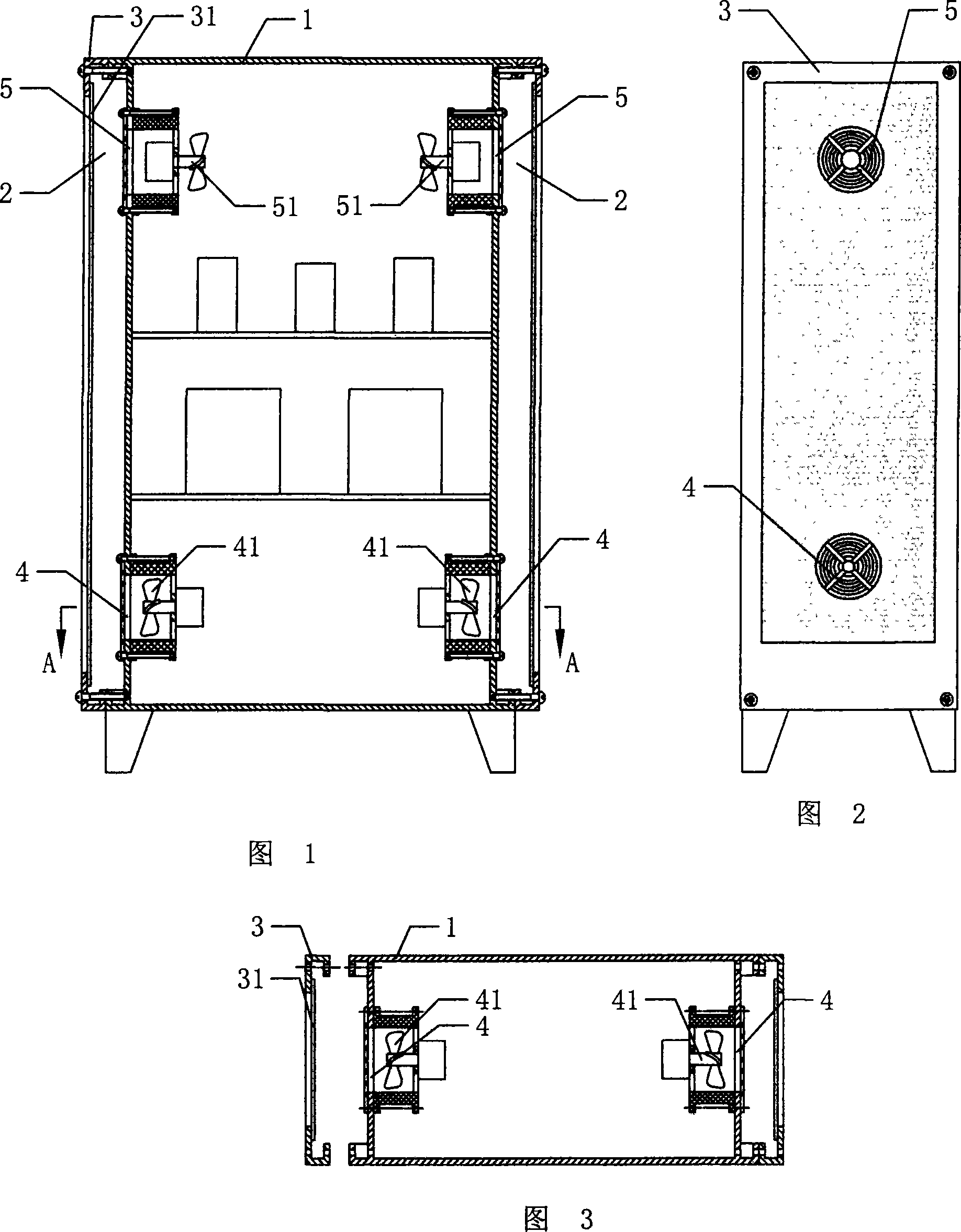
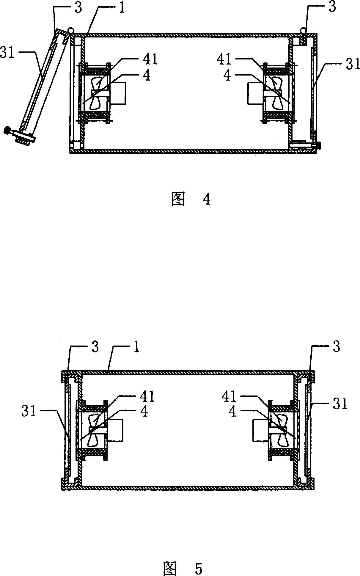
[0025] Embodiment 1: As shown in Figure 1, Figure 2 and Figure 3, the dust-proof electrical cabinet includes an electrical cabinet housing 1, a ventilation device arranged on the side wall of the electrical cabinet housing 1, and the housing 1 The side wall provided with the ventilation device has a ventilation cavity 2 communicated with the ventilation device, and the side wall of the ventilation cavity 2 is equipped with a ventilation cavity 2 communicating with the outside space. filter device. The air exchange cavity 2 is a cavity formed by the outward extension of the side wall of the shell 1 for air exchange; Net support 3, described filter net support 3 is provided with filter screen 31, and described filter screen support 3 is fixed on the side wall of described housing 1 by four screws, can be arranged on described filter net 31 like this When there is a lot of dust or damage, the filter screen support 3 can be removed in time to clean or replace the filter screen 31...

Embodiment 2

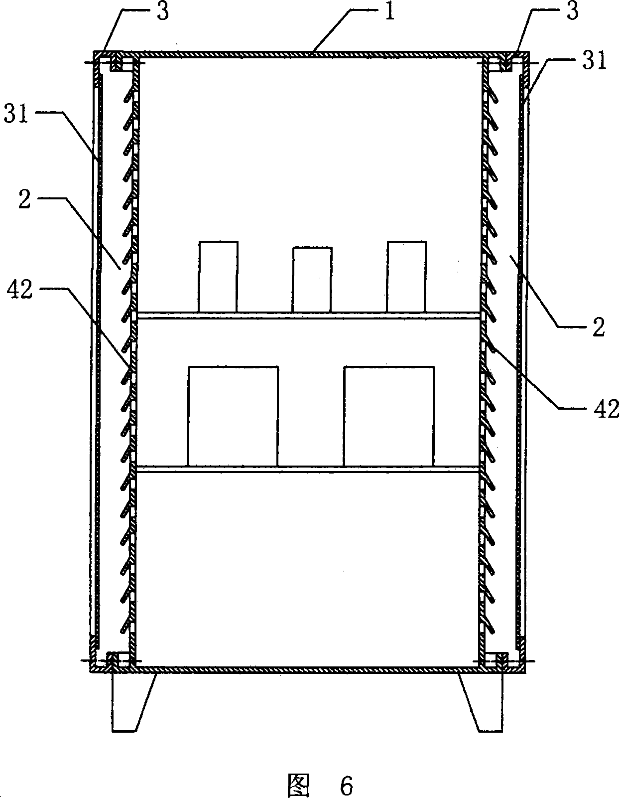
[0028] Embodiment 2: As shown in FIG. 6, the basic structure of the dust-proof electrical cabinet is basically the same as that of Embodiment 1, the difference is that the ventilation device is several hundreds of valves arranged on the two side walls of the housing 1. Page window 42, that is, the ventilation device described is a natural ventilation device. In an electrical cabinet that generates less heat, setting this ventilation device can save the power used for installing fans, etc., and can make the structure simple and the cabinet The inner space becomes larger, and the maintenance cost caused by fan failure and other problems is also saved.

Embodiment 3

[0029] Embodiment 3: As shown in FIG. 7 , the basic structure of the dust-proof electrical cabinet is basically the same as that of Embodiment 1, the difference is that the ventilation device includes an air inlet 4 arranged at the lower end of the side wall of the housing 1 , the air intake fan 41 fixedly installed at the air inlet 4, and a number of shutters 42 arranged on the upper ends of the two side walls of the housing 1. This kind of ventilation device enters the air through the air inlet 4 and enters the electrical cabinet. After sufficient heat exchange in the cabinet, the air in the cabinet is discharged through the louvers 42 on the upper ends of the two side walls of the housing 1 under the pressure of the air intake fan 41, which meets the requirements when the electrical cabinet generates more heat. , can get heat exchange in time, and increase the internal space of the electrical cabinet to a certain extent.


PUM


Abstract

This invention discloses a dustproof electric cabin including a shell, a ventilation device set on the side wall of the shell with cavities connected with the ventilation device, and a filter device connecting said ventilation cavity and outside space is set on the side wall of the cavity to filter air in the cavity by the filter device and cool electric appliances in the shell by the ventilation device to exchange air in and out of the electric cabin in large area and easily to increase radiation and ventilation result.

Description

technical field [0001] The invention relates to an electric cabinet, in particular to a dustproof electric cabinet. Background technique [0002] For all cabinets installed with electronic equipment, such as cabinets installed with high-power electronic components and communication equipment, if the heat generated by the equipment installed in the cabinet reaches a certain level, some kind of heat dissipation method must be used to discharge the heat. At present, the most common method is to use fan forced convection to dissipate heat. In order to prevent external dust from entering the cabinet to corrode and damage the equipment, in the prior art, a dust filter is installed at the air inlet to allow acceptable clean air to enter the cabinet. , and then exhaust the hot air through the air outlet. [0003] But for the dust-proof method in the prior art, there are many disadvantages: 1. The filter area is small, only filters the narrow area at the air inlet of the fan, and ca...

Claims


Application Information

Patent Timeline
Patent Type & Authority Applications(China)
IPC IPC(8): H05K7/20H02B1/28A47B81/06
Inventor 程培温王贵莲张立强宗洋薛霏
Owner 山东乐航节能科技股份有限公司
Why Eureka
Try Eureka