Protection circuit and battery pack

A technology for protecting circuits and circuit boards, applied to emergency protection circuit devices, circuits, secondary batteries, etc., can solve the problems of excessive circuit scale, battery expansion, low precision, etc., and achieve the effect of improving safety and reliability

Inactive Publication Date: 2007-12-19
PANASONIC CORP
View PDF1 Cites 13 Cited by
  • Summary
  • Abstract
  • Description
  • Claims
  • Application Information

AI Technical Summary

Problems solved by technology

[0012]However, in the protection circuit 102 shown in FIG. 12, since the FET contains a parasitic diode, it is impossible to use one FET to cut off the discharge current and the charge in which the current flows in different directions. current, so it is necessary to have FET106 to cut off the discharge current and FET107 to cut off the charge current
Moreover, a reference voltage source 108 and a comparator 110 are required to detect overcharge, a reference voltage source 109, a comparator 111, and a resistor 112 are required to detect an excessive discharge current, and output signals based on the comparators 110 and 111 are required. Since the logic circuit 113 turns on (ON) / off (OFF) the two FETs 106 and 107, there is a disadvantage that the circuit scale of the protection circuit 102 is too large
[0013] In addition, in the structure shown in FIG. 13 or FIG. 14, the secondary battery is protected from overcharging by connecting a temperature switch that operates according to the temperature of the PTC element and the like in series with the secondary battery to protect the secondary battery from overcharging. Low accuracy, for example, when using a charging device with poor charging voltage control accuracy to charge the battery pack, if the secondary battery is continuously charged with a charging current that does not rise in temperature rapidly, the temperature switch may not act. However, the secondary battery is overcharged, resulting in deterioration of the characteristics of the secondary battery, swelling or deformation of the battery, etc.

Method used


Image

  • Protection circuit and battery pack
  • Protection circuit and battery pack
  • Protection circuit and battery pack

Examples


no. 1 example

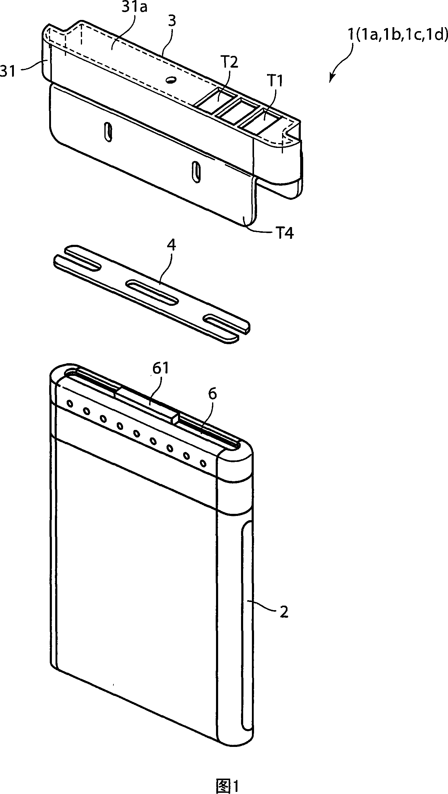
[0041] FIG. 1 is an exploded perspective view showing an example of a battery pack according to a first embodiment of the present invention. A battery pack 1 shown in FIG. 1 has a bottomed container 2 , an external connection terminal unit (Unit) 3 , and a plate-shaped spacer (Spacer) 4 inserted between the container 2 and the external connection terminal unit 3 . A secondary battery 6 is housed in the container 2 and sealed by crimping. A positive terminal 61 protruding from the secondary battery 6 protrudes from the open end of the container 2 . Furthermore, the container 2 is made of a nickel-plated steel plate, and the negative electrode of the secondary battery 6 is connected to the container 2 inside the container 2 .

[0042] The external connection terminal unit 3 has a case 31 formed of, for example, resin, and connection terminals T1 and T2 for connecting a charging device or a load device are provided so as to be exposed on the top of the case 31 . Furthermore, a c...

no. 2 example

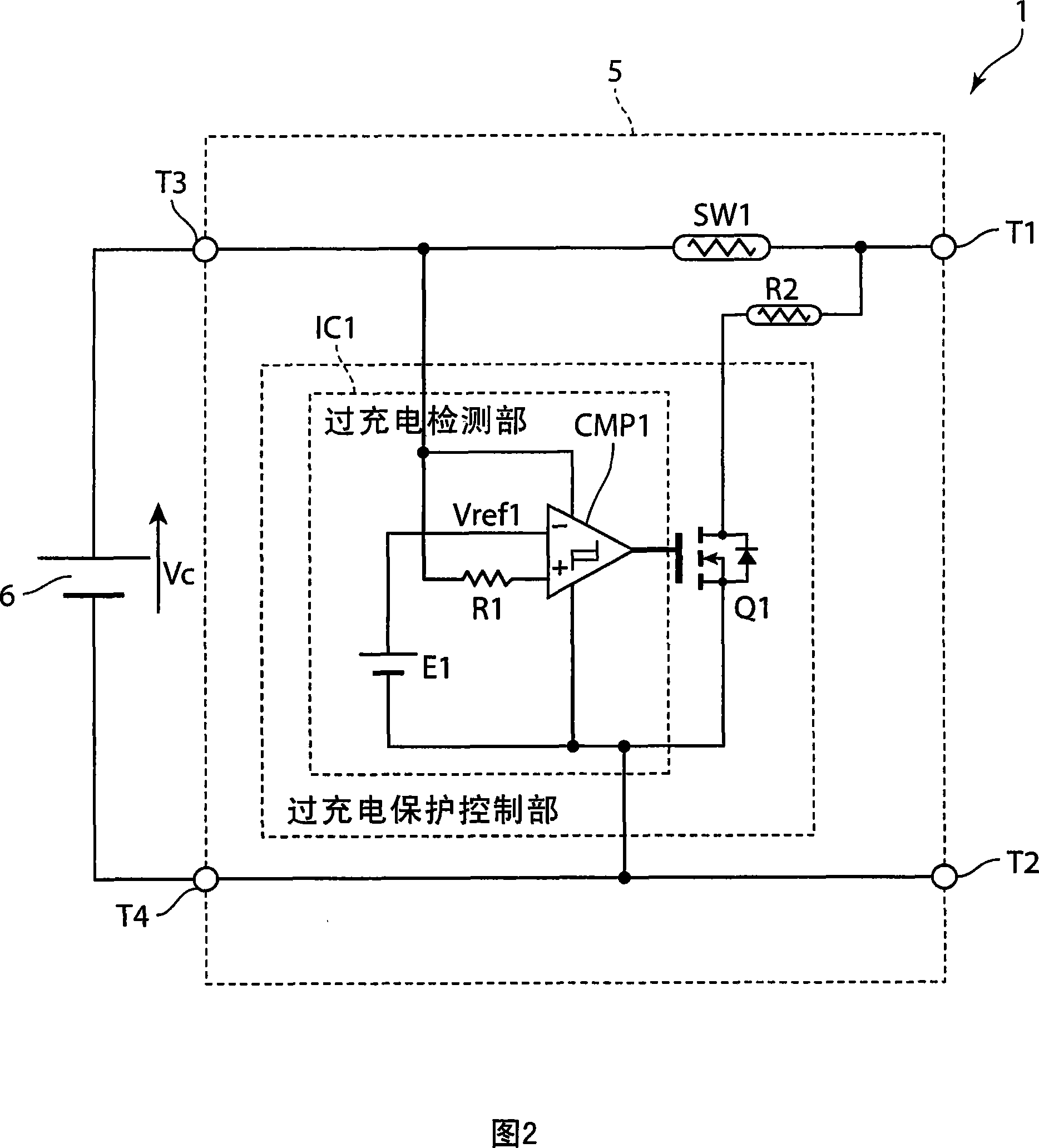
[0066] Next, a battery pack according to a second embodiment of the present invention will be described. The appearance of the battery pack 1a of the second embodiment of the present invention is the same as that of the battery pack 1 shown in FIG. 1 . FIG. 4 is a circuit diagram showing an example of an electrical configuration of a battery pack 1a according to a second embodiment of the present invention. The battery pack 1a shown in FIG. 4 differs from the battery pack 1 shown in FIG. 2 in the configuration of the protection circuit 5 . That is, in the protection circuit 5 of the first embodiment, the heater R2 is connected to the terminal on the side of the connection terminal T1 of the PTC element SW1, while in the protection circuit 5a of the second embodiment, the heater R2 is connected to the PTC element SW1. The characteristic of this embodiment is that the terminals on the side of the secondary battery 6 of the element SW1 are connected.

[0067] Next, the operatio...

no. 3 example

[0075] Next, a battery pack according to a third embodiment of the present invention will be described. The battery pack 1b of the third embodiment of the present invention has the same appearance as the battery pack 1 shown in FIG. 1 . FIG. 5 is a circuit diagram showing an example of an electrical configuration of a battery pack 1b according to a third embodiment of the present invention. The battery pack 1b shown in FIG. 5 is different from the battery pack 1 shown in FIG. 2 in the structure of the protection circuit 5b. That is, in the protection circuit 5b shown in FIG. 5, compared with the protection circuit 5, the heater R2 is removed, and the overcharge prevention transistor FET1 is connected to the PTC element SW1. The transistor (switching transistor) Q1 included in the integrated circuit IC1 is The characteristic of this embodiment is.

[0076] The overcharge prevention transistor FET1 is a p-channel field effect transistor, its gate is connected to the drain of t...


PUM


Abstract

A secondary battery is protected from being overcharged and excess discharge current by a simple circuit. A comparator (CMP1) compares a charging voltage (Vc) of the secondary battery (6) with a reference voltage (Vref1) and detects overcharge. A transistor (Q1) turns on and turns on a heater (R2) when overcharge is detected by the comparator (CMP1). A PTC element (SW1) turns off when it is heated by the heater and reaches a prescribed operation temperature (Tsw1), and interrupts a charging current. When the discharge current from the secondary battery (6) is excessive, the PTC element (SW1) self-heats by the discharge current and turns off when it reaches the operation temperature (Tsw1) and interrupts the discharge current.

Description

technical field [0001] The present invention relates to a protection circuit and a battery pack for protecting a secondary battery from overcharging or excessive discharge current. Background technique [0002] 12 is a circuit diagram showing the structure of a battery pack (Battery Packing) according to the background art. A battery pack 101 shown in FIG. 12 has a protection circuit 102 and a secondary battery 103 . The secondary battery 103 is, for example, a lithium ion (Lithium ION) secondary battery, a lithium polymer (Lithium Polymer) secondary battery, a nickel metal hydride (NickelHydrogen) secondary battery, or a nickel cadmium (Nickel Cadmium) secondary battery, etc. secondary battery. If such a secondary battery is overcharged or discharged with an excessively large current, it will lead to deterioration of characteristics such as cycle life, swelling and deformation of the battery, and the like. Here, the battery pack 101 has a protection circuit 102 that prot...

Claims


Application Information

Patent Timeline
Patent Type & Authority Applications(China)
IPC IPC(8): H02H7/18H02H3/20H01M10/44H02J7/00H01M10/48
CPCY02E60/10
Inventor 森猪一郎
Owner PANASONIC CORP
Why Eureka
Try Eureka