Check patentability & draft patents in minutes with Patsnap Eureka AI!

Resolver fixing structure

A fixed structure and resolver technology, which is applied in the direction of structure connection, instrumentation, and conversion sensor output, etc., can solve the problem of the reduction of the detection accuracy of the resolver, and achieve the effect of high detection accuracy

Active Publication Date: 2007-12-19
TOYOTA JIDOSHA KK +1
View PDF2 Cites 14 Cited by
  • Summary
  • Abstract
  • Description
  • Claims
  • Application Information

AI Technical Summary

Problems solved by technology

[0005] In the case where the resolver is fixed by press-fitting, when the resolver itself is directly press-fitted, distortion occurs at the stator core of the resolver to thereby cause the detection accuracy of the resolver to decrease

Method used


Image

  • Resolver fixing structure
  • Resolver fixing structure
  • Resolver fixing structure

Examples


no. 1 example

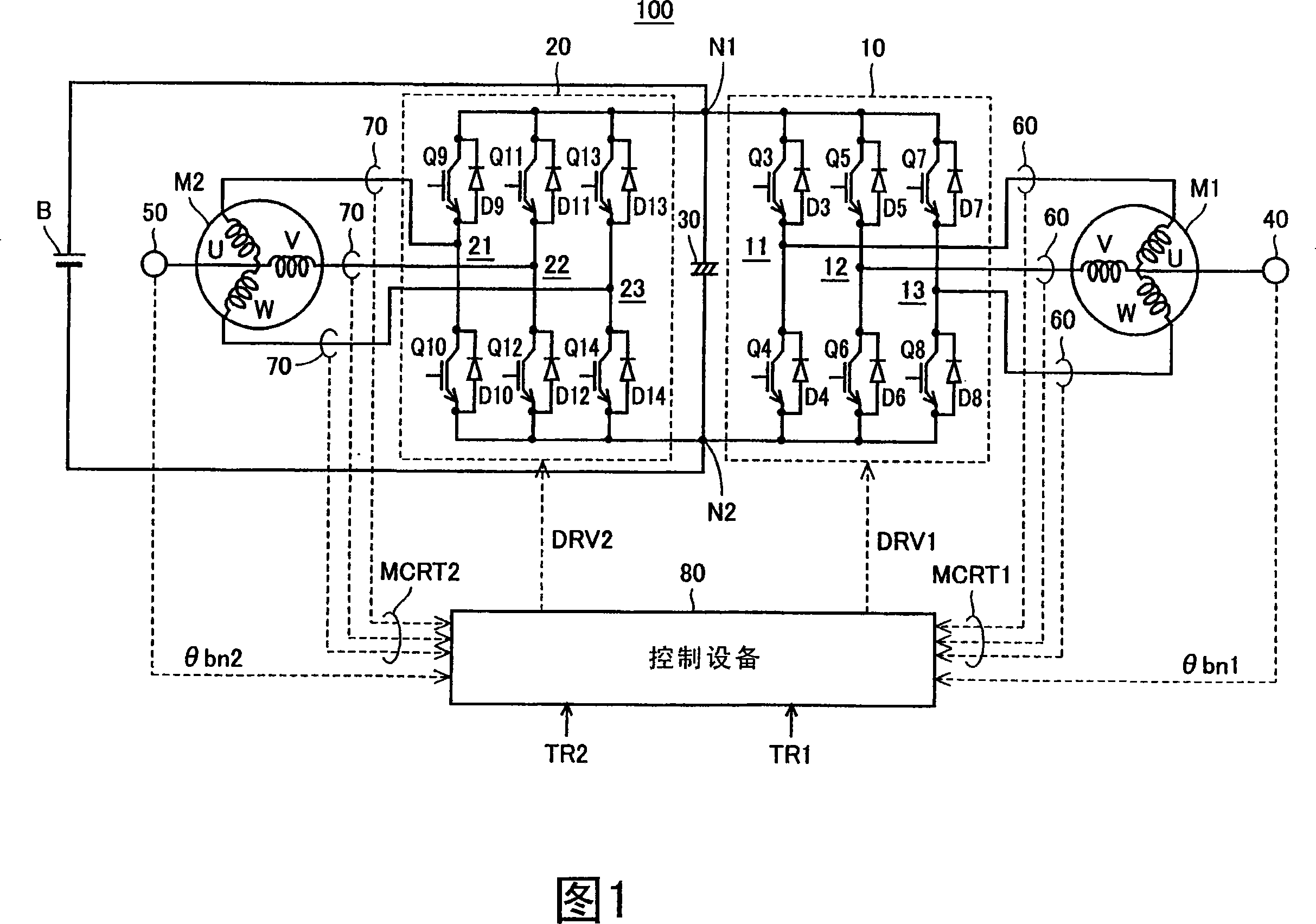
[0022] Fig. 1 is a block diagram of a motor drive device in which a resolver according to the present invention is used. Referring to FIG. 1, a motor drive device 100 according to a first embodiment of the present invention includes a direct current (DC) power source B, inverters 10 and 20, a capacitor 30, resolvers 40 and 50, current sensors 60 and 70, and a control device 80. .

[0023] Inverter 10 includes U-phase arm 11 , V-phase arm 12 and W-phase arm 13 . U-phase arm 11 , V-phase arm 12 , and W-phase arm 13 are connected in parallel between node N1 and node N2 .

[0024] U-phase arm 11 includes series-connected NPN transistors Q3 and Q4, V-phase arm 12 includes series-connected NPN transistors Q5 and Q6, and W-phase arm 13 includes series-connected NPN transistors Q7 and Q8. In addition, diodes D3-D8 are respectively connected between the collectors and emitters of the respective NPN transistors Q3-Q8 to supply current from the emitter side to the collector side.

[0...

no. 2 example

[0048] Fig. 5 is a perspective view of a resolver stator according to a second embodiment of the present invention. Referring to FIG. 5 , a resolver stator 41 according to a second embodiment of the present invention differs from the resolver stator 41 according to the first embodiment in that holes for inserting bolts therethrough are not provided. Since the resolver is conventionally fixed by means of an iron sheet called a resolver cover, through which a nut is inserted, long holes have to be provided in the stator part for inserting bolts therethrough and for adjusting the electrical zero position. This causes the size of the resolver to increase unnecessarily. That is to say, the outer diameter increases correspondingly to the elongated hole.

[0049] In the second embodiment employing the structure provided with the shielding member 242, the shielding member 242 is press-fitted to fix the resolver so that holes through which bolts are inserted are not required. In addi...


PUM


Abstract

The invention discloses a fixation structure of a resolver, which does not cause distortion at the place where the stator of the resolver is arranged. A resolver fixing structure disposed between coil ends (301) of a stator (302) constituting a rotating electric machine includes a ring portion (305) as a base member having a hole (310), and a ring portion (305) press-fitted into the hole (310) resolver stator (41). The resolver stator (41) has an outer peripheral portion provided with a shield member in contact with the hole (310).

Description

technical field [0001] The present invention relates to a resolver fixing structure, and more specifically, to a resolver fixing structure for detecting rotation of a rotating electrical machine. Background technique [0002] For example, conventional resolvers are disclosed in Japanese Patent Laid-Open No. 9-065617 (Document 1) and Japanese Utility Model Laid-Open No. 1-171563 (Document 2). [0003] Document 1 discloses a resolver-equipped motor provided with a shield member to cover a resolver coil. [0004] Document 2 discloses a structure in which the outer circumference of a resolver arranged between coil ends is covered with a magnetic shield plate. [0005] In the case where the resolver is fixed by press-fitting, when the resolver itself is directly press-fitted, twisting occurs at the stator core of the resolver to thereby cause the detection accuracy of the resolver to decrease. Contents of the invention [0006] The present invention aims to solve the above-me...

Claims


Application Information

Patent Timeline
Patent Type & Authority Applications(China)
IPC IPC(8): H02K24/00H02K5/04H02K11/00G01D5/245
CPCH02K7/20G01D5/2046H02K24/00H02K11/00H02K5/04G01D5/245
Inventor 塚岛浩幸牧内浩三
Owner TOYOTA JIDOSHA KK
Features
  • R&D
  • Intellectual Property
  • Life Sciences
  • Materials
  • Tech Scout
  • Unparalleled Data Quality
  • Higher Quality Content
  • 60% Fewer Hallucinations
Learn More