Single-ended to differential transducer circuit

A technology of balance converter and circuit, which is applied in the field of BALUN circuit, can solve the problems such as not being used to compensate current offset and the circuit cannot work, and achieve the effect of eliminating current offset and avoiding additional loss and phase error

Inactive Publication Date: 2010-05-26
NXP BV
View PDF4 Cites 0 Cited by
  • Summary
  • Abstract
  • Description
  • Claims
  • Application Information

AI Technical Summary

Problems solved by technology

[0007] However, the circuit of Figure 1 has the disadvantage that the circuit cannot operate at a minimum supply voltage of 1.6 volts, therefore, for linearity and matching purposes, a feedback resistor R2 is required
Furthermore, there is no means for changing the phase characteristics of the circuit to obtain broadband operation, moreover, there is no means for compensating the current offset after the two differential sections

Method used


Image

  • Single-ended to differential transducer circuit
  • Single-ended to differential transducer circuit
  • Single-ended to differential transducer circuit

Examples


Embodiment Construction

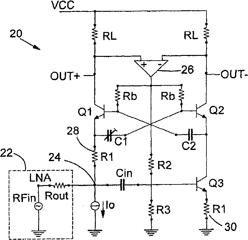
[0025] refer to figure 2 , a BALUN circuit 20 for receiving a single-ended radio-frequency output signal from a low-noise amplifier 22 (LNA) connected to an antenna (not shown), having: a first branch having a connection to a dual A current source Io for the emitter of transistor Q1. The collector of transistor Q1 is connected to voltage supply rail VCC through output terminal OUT+ and resistor RL. The second branch of the BALUN circuit has a transistor Q2 whose collector is connected to the voltage supply rail V through the output terminal OUT- and the resistor RL CC , and the emitter of the transistor is connected to the collector of transistor Q3. The emitter of transistor Q3 is connected to ground through resistor R130.

[0026] The voltage of the output terminal OUT+, OUT- is sensed by the input terminal of the operational amplifier 26, and the output signal of the amplifier is applied to the bases of the transistors Q1 and Q2 through the resistor Rb, and applied to th...


PUM


Abstract

A BALUN circuit (20) for low voltage operation for receiving single ended input signal at an input terminal (24) and providing a differential output signal across a pair of output terminals (OUT+, OUT-) is disclosed. The BALUN circuit (20) comprises a first branch including an input terminal (24) for receiving a single ended input voltage signal(RFin), a transistor (Ql), a resistance (Rl) (28), aresistance (RL), and an output terminal(OUT+). A second branch includes a transistor (Q3), a resistance (RL) and an output terminal(OUT-). An operational amplifier (26)maintains current flowing through the resistances RL in the first and second branches substantially equal to each other, in dependence upon the output voltage signal across the output terminals (OUT+, OUT-).

Description

technical field [0001] The present invention relates to unbalanced / balanced converter (BALUN) circuits, and in particular, but not exclusively, to BALUN circuits for connecting low noise amplifiers of radio frequency (RF) equipment to mixers. Background technique [0002] The RF signal provided by the antenna and LNA is usually single-ended, but a balanced circuit is usually used in the RF path of the integrated receiver / transmitter. Balanced circuits increase the immunity of RF circuits to common-mode disturbances and are therefore highly valued in RF circuit design. [0003] While differential antennas can be used to provide a balanced RF input signal, for simplicity a passive BALUN is often used to convert the unbalanced antenna signal into a balanced signal. However, the use of passive BALUNs has certain disadvantages. The passive balun is a lossy element whose loss occurs before the low noise amplifier to which the antenna is connected. Since the insertion loss is eq...

Claims


Application Information

Patent Timeline
Patent Type & Authority Patents(China)
IPC IPC(8): H03F1/32H03F3/19H03D7/14H03F3/45
CPCH03F2200/294H03F3/30H03F3/19H03F3/45H03F2200/513H03F2200/372H03F2200/06H03F1/22H03F3/343H03F1/3211H03F3/345
Inventor 米哈伊·A·T·森杜莱亚努爱德华·F·斯蒂克沃罗特
Owner NXP BV
Why Eureka
Try Eureka