Automatic air supply device for reducing cavitation vibration and noise of jet pump

A technology of automatic air replenishment and jet pump, which is applied in jet pumps, pumps, non-volume pumps, etc., to achieve the effects of reducing vibration and noise, high performance-price ratio, and simple structure

Inactive Publication Date: 2007-12-26
WUHAN UNIV
View PDF0 Cites 18 Cited by
  • Summary
  • Abstract
  • Description
  • Claims
  • Application Information

AI Technical Summary

Problems solved by technology

In short, the above method can improve the cavitation performance of the jet pump to a certain extent, but it does not fundamentally solve the problem

Method used


Image

  • Automatic air supply device for reducing cavitation vibration and noise of jet pump
  • Automatic air supply device for reducing cavitation vibration and noise of jet pump
  • Automatic air supply device for reducing cavitation vibration and noise of jet pump

Examples


Embodiment Construction

[0036] Further illustrate below in conjunction with accompanying drawing and embodiment:

[0037] 1. Overall

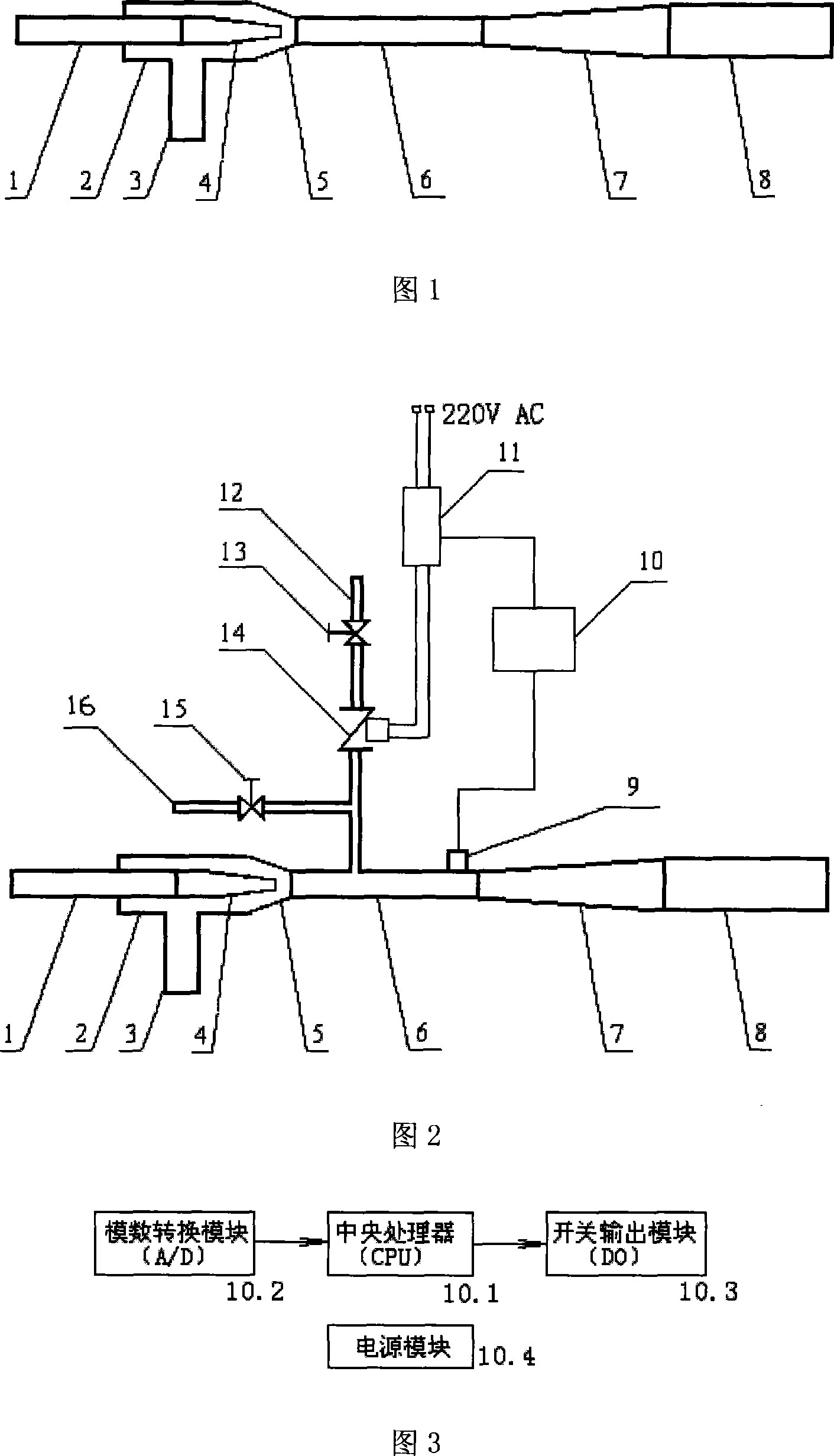
[0038] As shown in Fig. 2, the present invention is based on the conventional jet pump, and an automatic air supply device is set.

[0039] The automatic air supply device includes a pressure sensor (9), a PLC controller (10), a contactor (11), a main air intake pipe (12), a normally open valve (13), and a solenoid valve (14);

[0040] * On the main intake pipe (12), a bypass intake pipe (16) provided with a bypass valve (15) is connected through a three-way pipe. Once cavitation occurs in the jet pump, the 220V power supply loses power, or other failures occur, the solenoid valve (14) cannot be opened normally, and the outside air cannot be sucked by the main suction pipe (12), then the bypass valve (15) can be opened manually , outside air can also be sucked into the throat through the bypass pipe (16), thereby reducing the vibration and noise of the jet pump.

...


PUM


Abstract

This invention discloses an automatic air device reducing vapor-corrosion vibration and noises of jet pumps including a pressure sensor, a PLC controller, a contactor, a master intake pipe, a normal-open valve and an electromagnetic valve, in which the PLC controller includes CPU and A/D and DO connected with it and a supply module.

Description

technical field [0001] The invention relates to a liquid jet pump, in particular to an automatic air supply device capable of reducing vibration and noise induced by cavitation of the jet pump. Background technique [0002] Liquid jet pump (referred to as jet pump) is a kind of fluid conveying machinery and mixed reaction equipment that uses the turbulent diffusion of turbulent jet to transfer energy and quality. [0003] As shown in Figure 1, the typical structure of a conventional jet pump consists of a working water connection (1), a suction chamber (2), a suction pipe (3), a nozzle (4), a throat inlet pipe (5), a throat (6), a diffuser pipe (7) and outlet pipe (8); the working water connection pipe (1) and the nozzle (4) are connected and installed in the suction chamber (2); the suction chamber (2) is connected with a suction pipe (3), and the suction chamber ( 2), throat inlet pipe (5), throat pipe (6), diffusion pipe (7), and outlet pipe (8) are connected in sequence...

Claims


Application Information

Patent Timeline
Patent Type & Authority Applications(China)
IPC IPC(8): F04F5/10
Inventor 龙新平
Owner WUHAN UNIV
Why Eureka
Try Eureka