Power feeding equipment in high voltage / supervltage transmission system

A technology of power transmission system and power supply device, applied in battery circuit devices, circuit devices, systems for storing electrical energy, etc., can solve the problems of harsh natural environment, limited energy, electromagnetic interference of power supply circuits, etc. Simple and reliable, avoid the effect of electromagnetic interference

Inactive Publication Date: 2007-12-26
CHINA ELECTRIC POWER RES INST
View PDF0 Cites 16 Cited by
  • Summary
  • Abstract
  • Description
  • Claims
  • Application Information

AI Technical Summary

Problems solved by technology

[0003] 1. The large current and high field strength on the EHV transmission system platform will cause great electromagnetic interference to the power supply circuit, which requires the power supply device to have a strong ability to resist electromagnetic interference;
[0004] 2. The natural environment on the ultra-high voltage transmission system platform is harsh, which requires the power supply device to have the ability to withstand harsh environments such as high temperature, humidity, high cold, and ice
[0005] 3. Although the power supply can be easily obtained from the high-voltage line on the ultra-high voltage transmission system platform, because the power supply depends on the operation of the line, the work is not stable and reliable; Due to problems such as high voltage insulation, the energy sent to the platform becomes very precious and limited, which requires that the power supply and its monitoring circuit on the platform must have extremely low power consumption
It has the advantages of being free from electromagnetic interference, working status independent of lines, continuous and reliable power supply, etc.; the disadvantage is that the continuous working life is short, the cost is high, and the control is more complicated.

Method used


Image

  • Power feeding equipment in high voltage / supervltage transmission system
  • Power feeding equipment in high voltage / supervltage transmission system
  • Power feeding equipment in high voltage / supervltage transmission system

Examples


Embodiment Construction

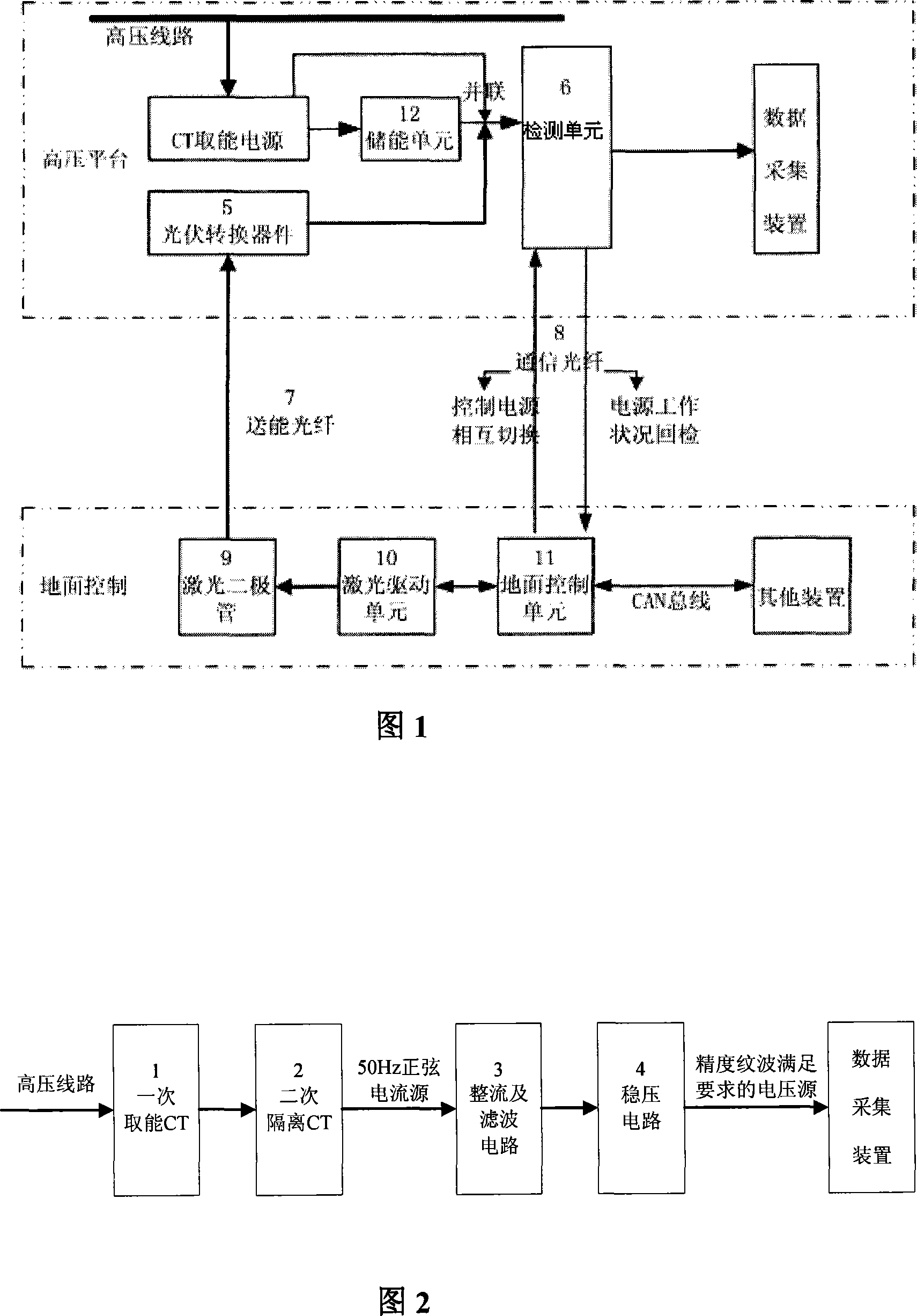
[0028] The power supply device of the present invention includes a laser energy transmission power supply, a CT (current transformer) energy acquisition power supply connected in parallel with the laser energy transmission power supply, and a device for monitoring and controlling the working conditions of the parallel circuit between the laser energy transmission power supply and the CT energy acquisition power supply. unit. The laser energy transmission power supply and the CT energy acquisition power supply are connected in parallel to jointly supply power to the load on the high-voltage platform, and at the same time transmit energy and information to the ground equipment through the energy transmission optical fiber and the communication optical fiber. Fig. 1 shows the principle block diagram of the power supply device of the present invention, which mainly completes obtaining energy from the high-voltage line and converting it into direct current through rectification and ...


PUM


Abstract

The power feeding equipment (PFE) includes a laser energy delivering power supply (LEDPS), a CT energy taking power supply (ETPS) connected to LEDPS in parallel, and a unit for monitoring and controlling working conditions of parallel circuit between LEDPS and ETPS. The function for monitoring and controlling the parallel circuit realizes automatic switching between LEDPS and ETPS based on actual working conditions. Being independent on working conditions of circuitry of high voltage / super voltage transmission, PFE can supply power for high voltage / super voltage transmission continuously. PFE also includes an energy storage unit in use for making smoothly and seamlessly switching between LEDPS and ETPS for load. Features of PFE are: long continuous service life, and lower cost.

Description

technical field [0001] The invention relates to a power supply device, in particular to a power supply device for a high-voltage / ultra-high voltage power transmission system. Background technique [0002] High-voltage / ultra-high-voltage transmission systems (devices), such as controllable series compensation / fixed series compensation devices for ultra-high-voltage AC transmission lines, the data acquisition devices used in the measurement part are active measurement methods, which requires The data acquisition device provides power. The power supply mode of the device on the EHV transmission system platform is different from that of the ground power system, and it has the following characteristics: [0003] 1. The large current and high field strength on the EHV transmission system platform will cause great electromagnetic interference to the power supply circuit, which requires the power supply device to have a strong ability to resist electromagnetic interference; [000...

Claims


Application Information

Patent Timeline
Patent Type & Authority Applications(China)
IPC IPC(8): H02J11/00H02J9/00H02J15/00H02J7/35
CPCY02E70/30Y02E10/566Y02E10/56
Inventor 刘慧文袁洪亮
Owner CHINA ELECTRIC POWER RES INST
Why Eureka
Try Eureka