Film letting-off device for roll baler, and method for winding film on rolled bale

A wrapping machine and film technology, which is applied in the field of film output devices, can solve the problems of film stretching, excessive sliding resistance, and being wound, and achieve the effects of eliminating film damage and reducing frictional resistance

Active Publication Date: 2008-01-02
德佳达有限公司
View PDF1 Cites 34 Cited by
  • Summary
  • Abstract
  • Description
  • Claims
  • Application Information

AI Technical Summary

Problems solved by technology

(1) Since the brake arm shaft 23 is a non-rotating structure, the sliding resistance will not be too large even when the net N is not fully contacted, so that the net N can slide on the brake arm shaft 23 while However, in the case of a film, since it is in full contact with the brake arm shaft 23, the sliding resistance becomes too large, and the film cannot be slid with respect to the brake arm shaft 23 of a non-rotating structure for output.
(2) For substantially the same reason, the outer peripheral contact plate 28 for detecting the winding diameter of the web roll R', which becomes smaller with time, slides on the outer peripheral surface of the web roll R' that rotates. Contact, in the case of a net N, is not a problem because the sliding resistance against the outer peripheral contact plate 28 is small, but in the case of a film, the sliding resistance against the outer peripheral contact plate 28 becomes too large, and the film itself is affected. damage
[0009] Like this, can't directly use the net output device A " shown in Fig. 19 to carry out the output of film
[0010] On the other hand, for "film winding", since the film and the feed are not integrated, it has the above-mentioned advantages that only the film can be pulled and peeled off relatively easily to disassemble the drum bundle. However, in the "film winding" In the case of low temperature, the film is easy to adhere to moisture such as fog and rain, and it is easy to generate static electricity
Therefore, there is a problem that the film cannot be smoothly fed out because it is wound on rollers during the travel of the film travel path.
In addition, since the film is easily stretched by the wind, there is also a problem that both ends in the width direction of the film are folded and overlapped, or the film is wound up sticky.
The latter problem is especially likely to occur at the time when the film is wound on the drum roll and ends when the tension acting on the film is small or almost non-existent.

Method used


Image

  • Film letting-off device for roll baler, and method for winding film on rolled bale
  • Film letting-off device for roll baler, and method for winding film on rolled bale
  • Film letting-off device for roll baler, and method for winding film on rolled bale

Examples


Embodiment Construction

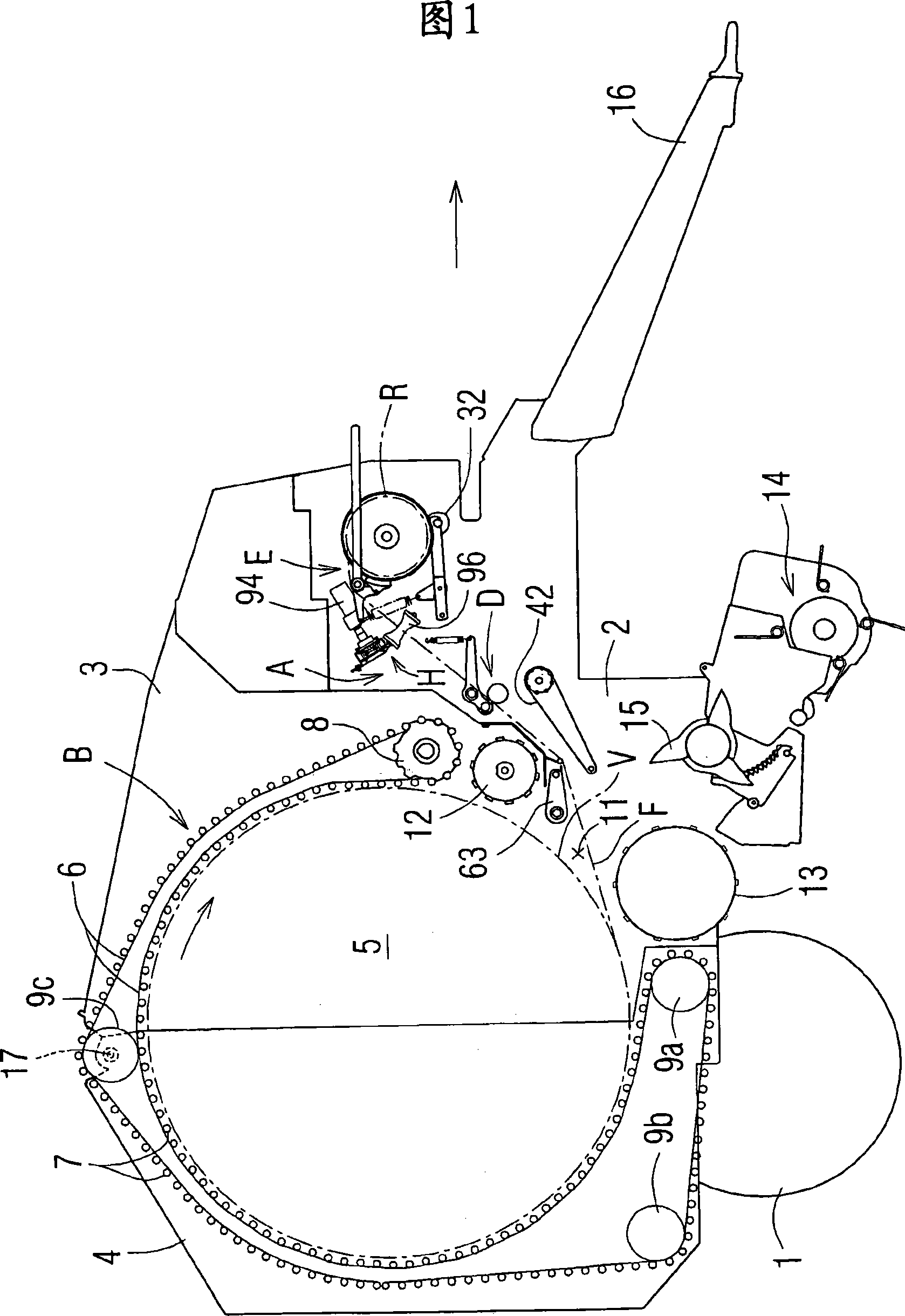
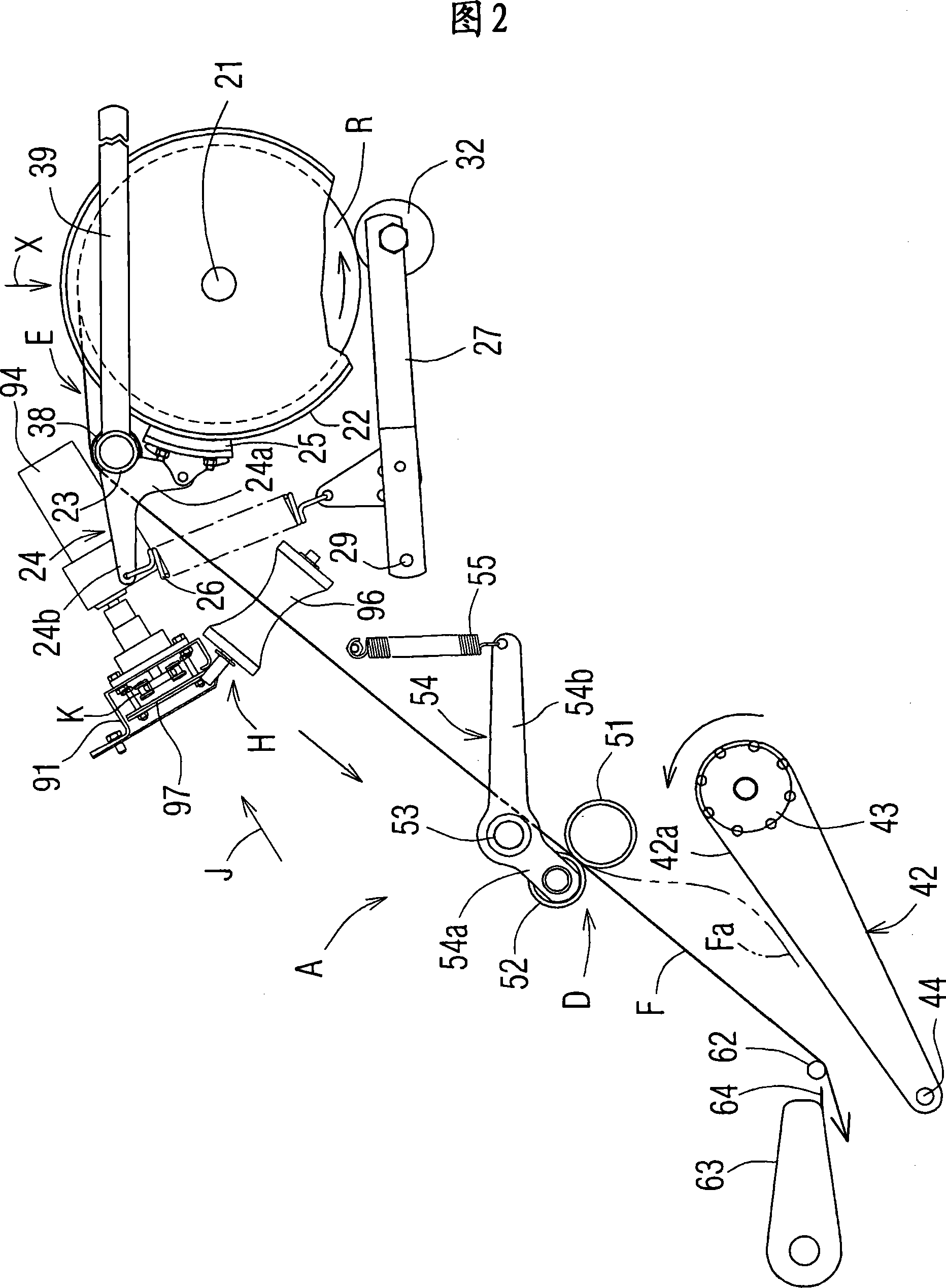
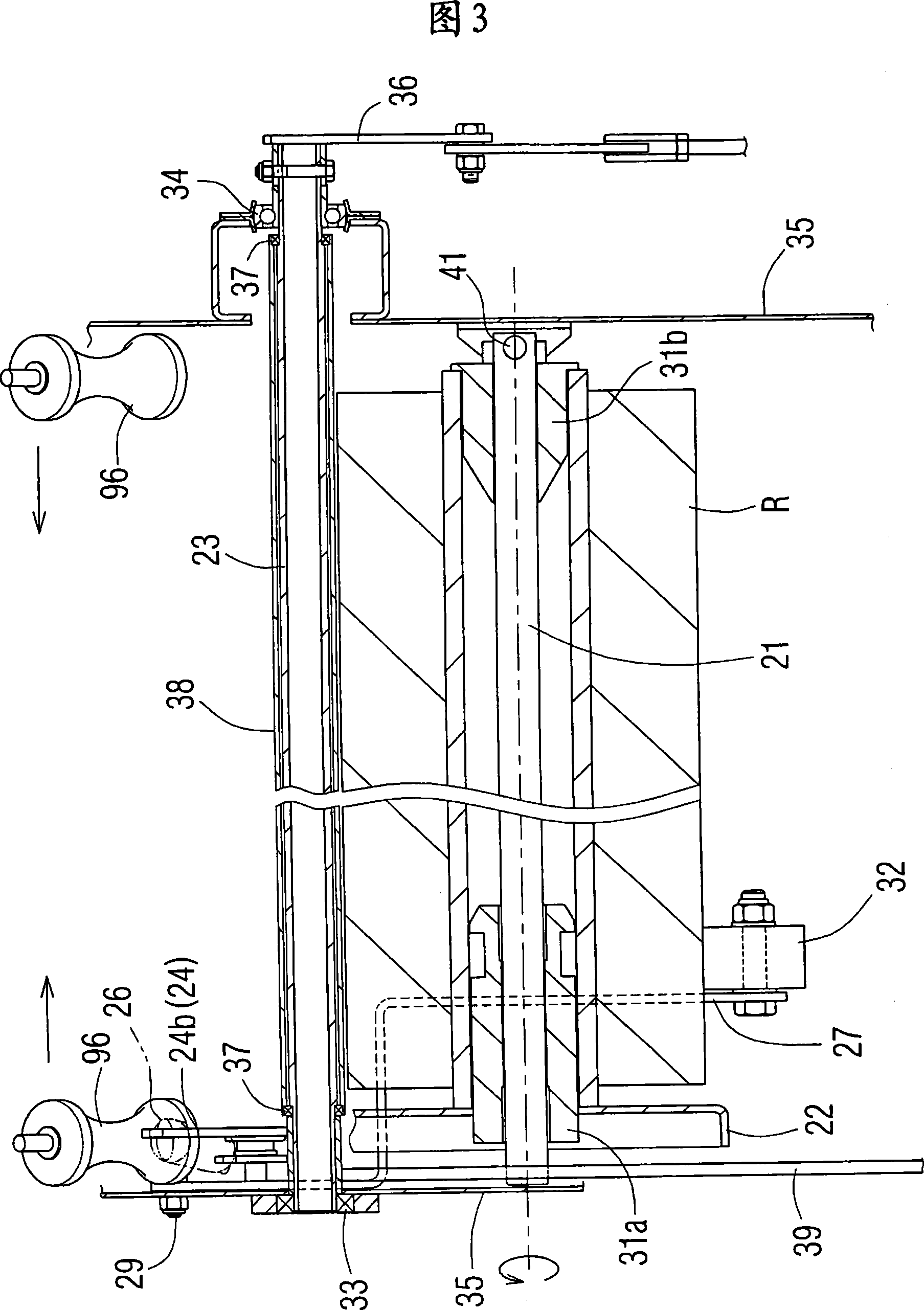
[0176] Hereinafter, the present invention will be explained in more detail by listing preferred embodiments. First, referring to FIGS. 1 to 4, the film discharge device A of the present invention will be described. Fig. 1 is an overall view of a roll bundle provided with a film discharge device A of the present invention. Fig. 2 is an enlarged view of the film discharge device A. 3 is a cross-sectional view taken along the line X of FIG. 2 (a top cross-sectional view of the roll film drum device E). 4 is a partial perspective view of the brake shoe 25 side of the roll film drum device E. In the description of the film discharging device A, the same or equivalent parts as the existing net discharging device A" use the same reference numerals and refer to the above description, and only the parts specific to the film discharging device A of the present invention are used. A detailed description will be given. First, the overall general structure of the winder will be briefly describ...


PUM


Abstract

Provided is a film letting-off device for a rolled bale V, which is arranged immediately upstream of a roll baling device B for covering and wrapping the outer circumference of the rolled bale V with a film F, for letting off said film F. A width reducing device H, which is constituted such that a pair of width reducing rollers 96 arranged in the widthwise direction of the film F so as to reduce the width of the film F being let off from a film rolling device E, while said rolled bale V is being covered with the film F, are brought close to and apart from each other while being centered, is arranged between said film rolling device E and said drive roller device D.

Description

Technical field [0001] The present invention relates to a device for wrapping a film on the outer peripheral surface of a roller bundle formed by compression-molding forages into a roller shape by a roller bundling forming device, and arranging it on the front side of the roller bundling forming device to output the film The film output device of the roll baler and the method of winding the film on the roll bale. Background technique [0002] The roller baler uses a picking device to pick up the forages that have been cut down in the field, put it into the compression molding room, and compress it into a roller-shaped bale by means of a plurality of forming rods running around the compression molding room. After that, in order to prevent the "scattering" of the roll bundle, the outer circumference of the bundle is packed. As this packing operation of the conventional roller winding bale, there are "twine winding" in which a rope called twine is wound on the outer circumferential ...

Claims


Application Information

Patent Timeline
Patent Type & Authority Applications(China)
IPC IPC(8): B65B41/12B65B13/02B65B11/00B65B27/12B65H16/00B65H20/02B65H23/02B65H35/06A01F15/07
Inventor 生田良仁吉田秀则藤长涉白崎芳晴
Owner 德佳达有限公司
Why Eureka
Try Eureka