
Saw-tooth wire for producing a saw-tooth all-steel clothing for a roller or a carding element of a spinning room machine

A carding element, zigzag technology, used in fiber processing, heat treatment furnaces, heat treatment equipment, etc., can solve the problems of producing different types of card clothing, lowering manufacturing accuracy, high equipment wear, etc., to improve wear resistance and service life. , Improve quality, prolong the effect of cycle

Inactive Publication Date: 2008-01-02
TRUETZSCHLER GRP SE
View PDF1 Cites 23 Cited by
  • Summary
  • Abstract
  • Description
  • Claims
  • Application Information

AI Technical Summary

Problems solved by technology

Disadvantage is high wear on equipment
This equipment is frequently reground or replaced
In addition, wear reduces the precision of the manufacturing, from the beginning to the end of the card clothing, there are several kilometers in total, and each card clothing is different
Another disadvantage is that different machines can only produce different types of card clothings
Finally, the subsequent "flame" hardening of the teeth is a further production step, but also relatively imprecise and difficult to produce consistent results

Method used


Image

  • Saw-tooth wire for producing a saw-tooth all-steel clothing for a roller or a carding element of a spinning room machine
  • Saw-tooth wire for producing a saw-tooth all-steel clothing for a roller or a carding element of a spinning room machine
  • Saw-tooth wire for producing a saw-tooth all-steel clothing for a roller or a carding element of a spinning room machine

Examples


Embodiment Construction

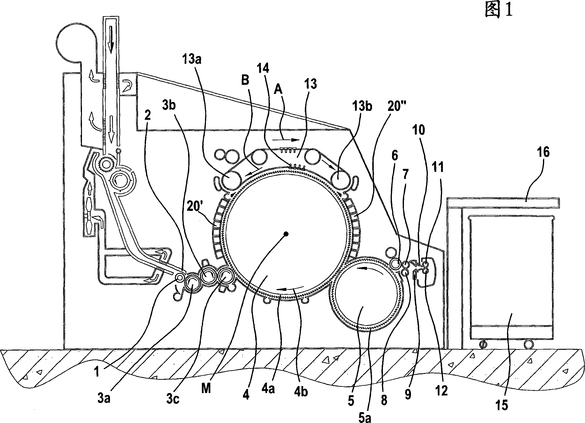
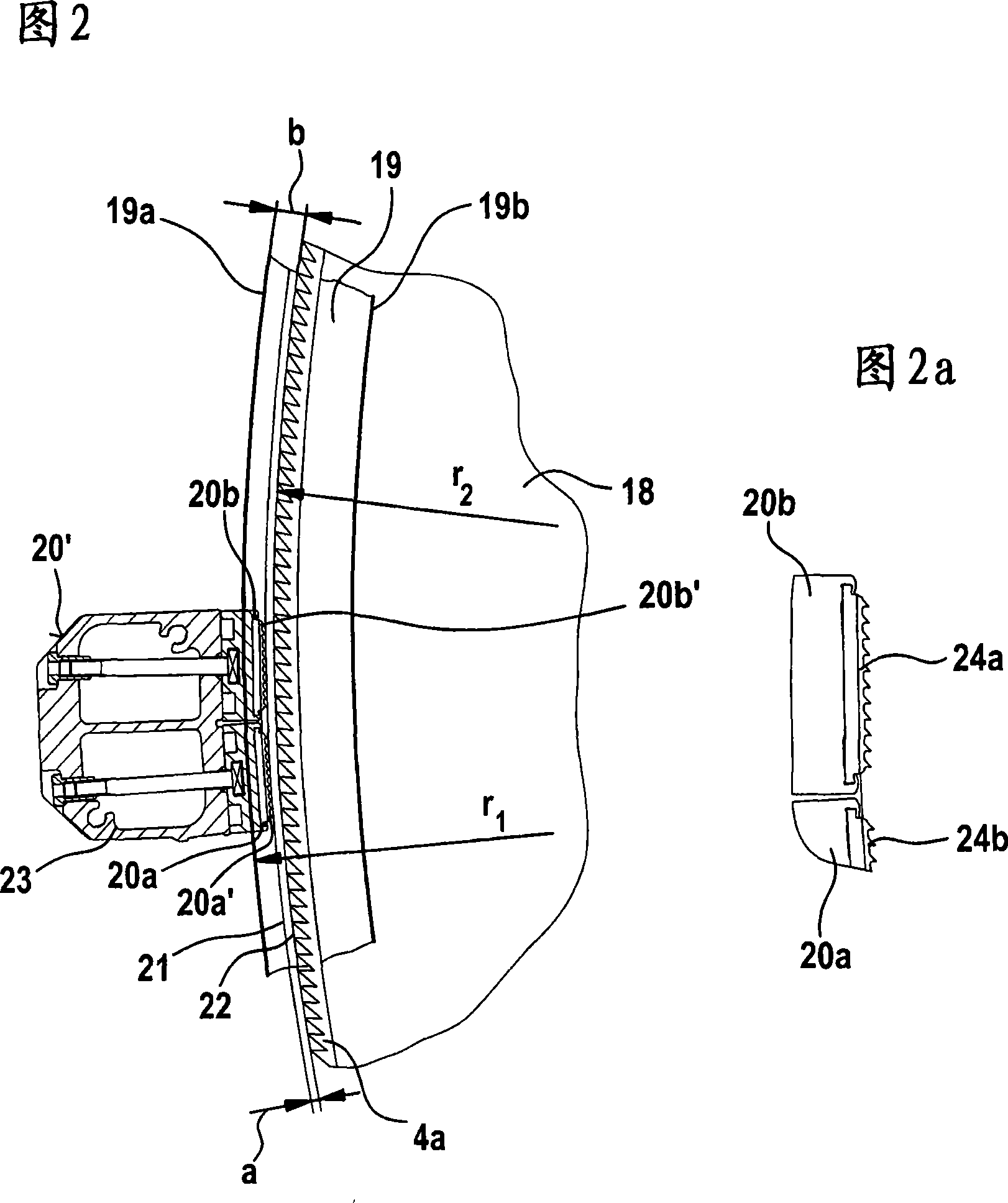
[0027] Figure 1 shows a flat card, e.g. Trützschler card TC 03, with feed roller or drum 1, feed plate 2, lickers 3a, 3b, 3c, cylinder 4, doffer 5, stripping roller Or drum 6, pressing rollers 7, 8, web guide elements 9, web horn 10, delivery rollers or drums 11, 12, revolving flat 13 with flat guide rollers 13a, 13b and flat strips 14, can 15 and coiler 16. The direction of rotation of each roller or drum is indicated by the corresponding curved arrow. Letter M represents the exact center (axis) of cylinder 4. The numeral 4a represents the card clothing, and 4b represents the direction of rotation of the cylinder 4 . The letter A indicates the direction of work. Curved arrows on each roller or drum indicate the direction of rotation of the roller or drum. Between the lancet 3c and the rear flat guide roller 13a, and between the doffer 5 and the front flat guide roller 13b, a plurality of fixed carding elements 20 are arranged facing the cylinder 4 I and 20 II (See Figur...


PUM


Abstract

In the case of a saw-tooth wire for producing a saw-tooth all-steel clothing for a roller or a carding element of a spinning room machine, having an elongate base region (foot) and an adjoining toothed region (blade) in which teeth are formed by cutting, the teeth comprising a tooth front, a tooth back and two side flanks, between the tooth back and the tooth front of two successively arranged teeth there is a gullet. To produce a saw-tooth wire, which comprises in particular teeth of exact and uniform tooth geometry, the teeth of the saw-tooth wire are made by treating with a laser device.

Description

technical field [0001] The present invention relates to a zigzag steel wire, which is used to produce zigzag all-steel card clothing on rollers or drums or carding elements of flat carding machines, roller carding machines, cleaning machines, cotton openers and other machines in spinning workshops, Has an elongated base region (bottom) and an adjacent tooth region (plate part), in which the sawtooth is formed by cutting, the sawtooth includes the tooth front, tooth back and two sides, in two consecutive rows There is an inter-tooth space between the tooth back and the tooth front of the sawtooth; the invention also includes a method and an apparatus for producing a sawtooth steel wire. Background technique [0002] For example, all-steel card clothings of zigzag wires are used in the process of using textile fibers to make yarns, nonwovens or other similar products. In this case, the individual sawtooth wires, for example, have a height of less than 2 mm and a width of 0.2 ...

Claims


Application Information

Patent Timeline
Patent Type & Authority Applications(China)
IPC IPC(8): D01G15/84D01G15/88B23K26/36B23K26/08B23K26/04B23K26/06B41M5/24C21D1/09
CPCB23D65/02C21D9/26C21D1/09D01G15/88
Inventor H·罗泽曼
Owner TRUETZSCHLER GRP SE
Learn More