Technology for reducing resistance force of DC waterproof pump controlling valve

A control valve and resistance technology, which is applied in pump control, components of pumping devices for elastic fluids, non-variable-capacity pumps, etc., can solve the problems of large shape resistance, etc. reduced effect

Inactive Publication Date: 2008-01-02
SHANGHAI SHANGLONG VALVE FACTORY
View PDF0 Cites 0 Cited by
  • Summary
  • Abstract
  • Description
  • Claims
  • Application Information

AI Technical Summary

Problems solved by technology

[0002] At present, all kinds of water pump control valves generally have the defect of large shape resistance when water is normally passed through.

Method used


Image

  • Technology for reducing resistance force of DC waterproof pump controlling valve

Examples


Embodiment Construction

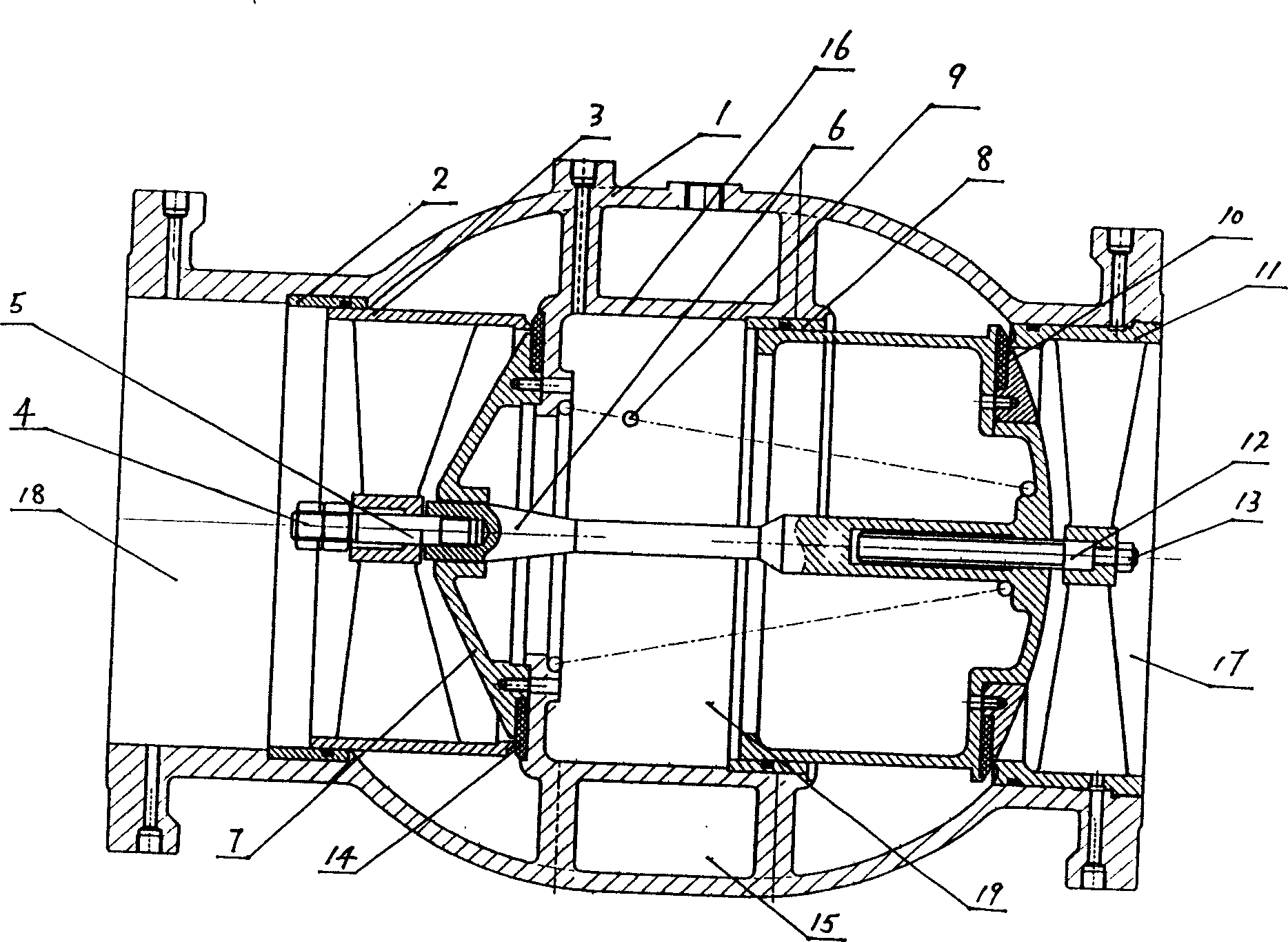
[0008] A technology for reducing resistance of a direct-flow water pump control valve mainly includes the following steps: the inlet disc is provided in an arc shape, the conical cover is in a conical shape, and the two form a guiding body. The structure of the low-resistance once-through water pump control valve manufactured by the present invention will be further described in detail below in conjunction with the accompanying drawings. Referring to the accompanying drawings, a low-resistance DC water pump control valve, the valve body 1 is provided with an inlet port 17 and an outlet port 18, and the inlet port 17 is provided with an inlet valve seat 11, and the inlet valve seat 11 and the inlet valve disc 10 form a first First-level sealing, the inlet disc 10 is set in the valve inner sleeve 16 on the valve body 1, the inlet valve disc sleeve 8 is set between the inlet valve disc 10 and the valve inner sleeve 16, and the valve inner sleeve 16 is provided near the outlet end ...


PUM


Abstract

The invention discloses a technique to decrease resistance of straight-flow type water pump controlled valve, which comprises the following steps: setting the intake valve clap as circular arc; setting cone lid as cone; forming a flow guiding body with the intake valve clap and the cone lid. This invention possesses reasonable craft and good idea, which can be spreaded widely.

Description

technical field [0001] The invention relates to the technical field of valve manufacturing, in particular to a technology for reducing resistance of a water pump control valve. Background technique [0002] Current various water pump control valves generally have the defect of large shape resistance when water is normally passed through. Contents of the invention [0003] The object of the present invention is to provide a resistance reduction technology of a once-through water pump control valve that can effectively overcome the above-mentioned defects and has a small shape resistance during normal water flow. [0004] In order to achieve the above object, the present invention adopts the following technical solution: a technology for reducing resistance of a straight-through water pump control valve, which mainly includes the following steps: the inlet disc is provided in an arc shape, the conical cover is in a conical shape, and the two forms A diverter. [0005] Due ...

Claims


Application Information

Patent Timeline
Patent Type & Authority Applications(China)
IPC IPC(8): F04D29/00F04D15/00
Inventor 季能平
Owner SHANGHAI SHANGLONG VALVE FACTORY
Why Eureka
Try Eureka