Heat sink and cooling unit using same

A technology of heat dissipation device and cooling unit, which is applied in cooling/ventilation/heating transformation, electrical components, electric solid devices, etc., can solve the problems of increasing temperature difference of heating element mounting surface, increasing volume of heat dissipation device, and high temperature of cooling fluid , to achieve the effect of excellent thermal uniformity and compact thermal uniformity

Inactive Publication Date: 2008-01-02
MITSUBISHI ELECTRIC CORP
View PDF1 Cites 3 Cited by
  • Summary
  • Abstract
  • Description
  • Claims
  • Application Information

AI Technical Summary

Problems solved by technology

Therefore, in the case where headers are formed at both ends of the heat transfer container, since the headers are respectively formed at both ends of the heat transfer container, there is an accessible area around the heating element mounted on the heat transfer container. There are few surfaces, or there is a problem of useless space on the back of the heating element installation part
[0007] In addition, when the inlet side part and the outlet side part of the cooling fluid are separately arranged on one side of the heat transfer container, since the flow path in the heat transfer container becomes a long serial flow path, the cooling fluid In the process of passing through the flow path of the heat transfer container, the heating element receives heat and heats up, and the temperature of the cooling fluid at the outflow part is higher than that of the inflow part of the cooling fluid, so there is a temperature difference in the heating element installation surface Bigger problem
In addition, in order to solve this problem, when a plurality of flow paths are formed in the heat transfer container to form parallel flow paths, since each flow path is staggered or multiple U-shaped turning parts are formed, there is a problem that the volume of the heat sink becomes larger. The problem

Method used


Image

  • Heat sink and cooling unit using same
  • Heat sink and cooling unit using same
  • Heat sink and cooling unit using same

Examples


Embodiment Construction

[0038] Implementation form 1.

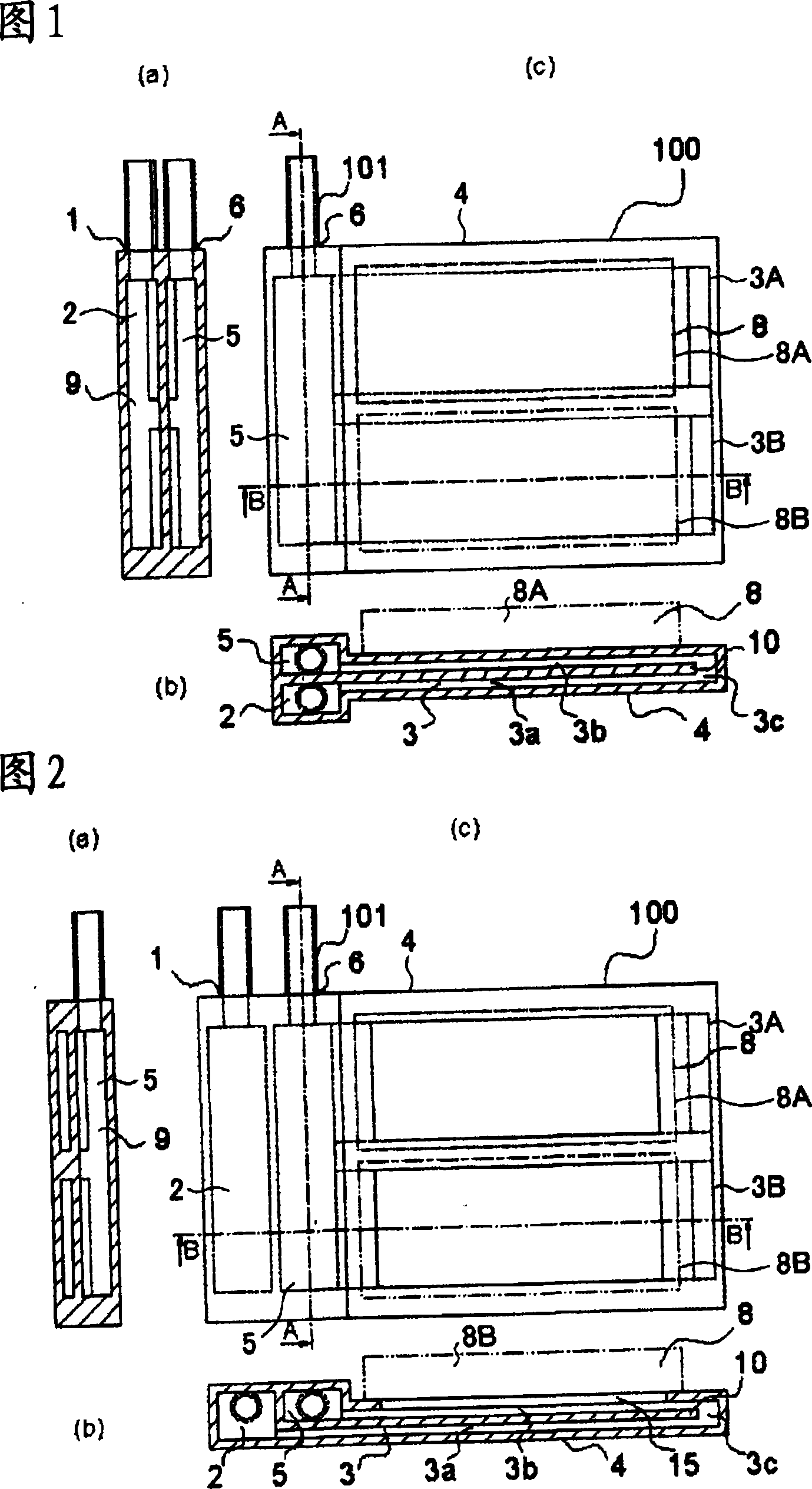
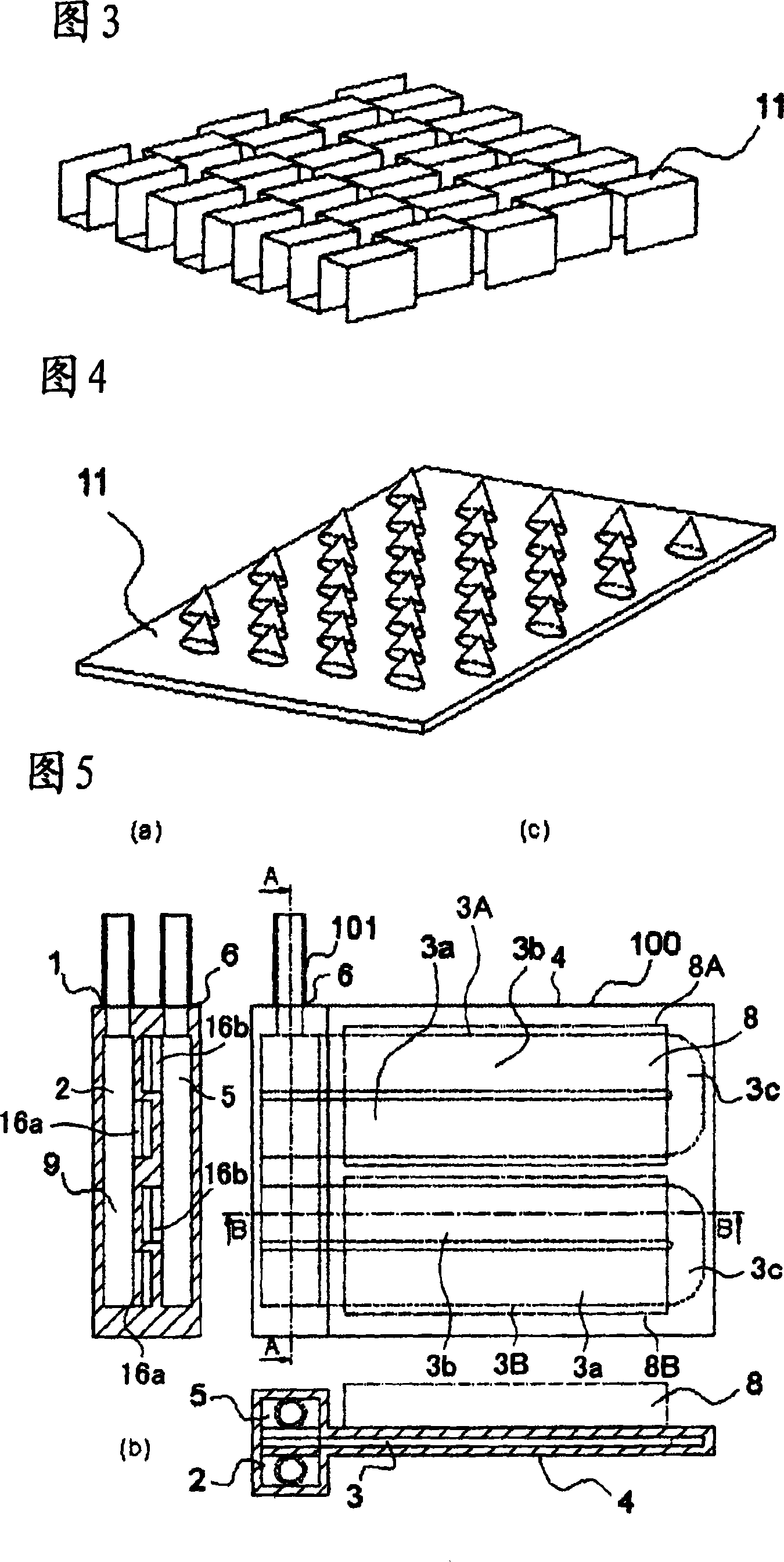
[0039] Fig. 1 is a structural diagram schematically showing a heat dissipation device according to Embodiment 1 of the present invention, Fig. 1(c) is a diagram seen when observing the heat dissipation device from above, Fig. 1(a) is a diagram in Fig. The sectional view at the line A-A in Fig. 1(b) is the sectional view at the line B-B in Fig. 1(c). In addition, Fig. 2 is a diagram showing another structure of the heat sink according to Embodiment 1 of the present invention, Fig. 2(c) is a diagram seen when the heat sink is viewed from above, Fig. 2(a) is a 2(c) is a sectional view at the line A-A, and FIG. 2(b) is a sectional view at the line B-B in FIG. 2(c).

[0040]In FIGS. 1 and 2 , the heat sink 100 constitutes a cooling system for cooling the heat generating element 8 mounted thereon. The cooling device 100 is composed of the following parts to form a serial flow path: the cooling fluid inlet 1 for sending in the low-temperature cooling...


PUM


Abstract

A heat sink which can make a cooling system compact and has excellent heat uniformity, and a cooling unit which is compact and has excellent heat uniformity are provided. The heat sink (100) is composed of a distribution header (2) connected to a cooling fluid inlet (1); a merging header (5) which is connected to the cooling fluid outlet (6) and is adjacently arranged parallel to the distribution header (2); and a heat transferring container (4) having a heat generator attaching plane, and a flow path (3) connected to the distribution header (2) and the merging header (5) inside.

Description

technical field [0001] The present invention relates to a heat sink for cooling a heat generating body composed of electronic devices, and more particularly, to a heat sink with a structure for cooling by forced convection. In addition, it relates to a cooling unit connected to such a heat sink. Background technique [0002] Such a conventional heat sink is disclosed in Japanese Unexamined Patent Application Publication No. 2002-170915 (hereinafter referred to as prior art). This existing heat sink is equipped with a heat transfer container that forms a flow path inside and a heat transfer promoter (fins or turbulence promoters, etc.) The fluid inlet-side space and the cooling fluid outlet-side space cool the substrate by allowing the cooling fluid to flow from the inlet-side space to the outlet-side space, thereby cooling electronic devices mounted on the substrate. The inlet space side of the cooling fluid and the outlet side space of the cooling fluid, as shown in FIG. ...

Claims


Application Information

Patent Timeline
Patent Type & Authority Applications(China)
IPC IPC(8): H01L23/473H05K7/20
CPCH01L2924/0002H01L23/473H01L2924/00H05K7/20
Inventor 一法师茂俊山田晃田中毅村端章浩东矢和义冈山秀夫
Owner MITSUBISHI ELECTRIC CORP
Why Eureka
Try Eureka