Surgical instrument positioning method using infrared reflecting ball as symbolic point

A technology of surgical instruments and positioning methods, which is applied in the direction of surgery, instruments, applications, etc., can solve problems such as large errors and noise interference, and achieve the effect of reducing movement restrictions and expanding the effective working range

Inactive Publication Date: 2008-01-09
SHANGHAI JIAO TONG UNIV
View PDF0 Cites 42 Cited by
  • Summary
  • Abstract
  • Description
  • Claims
  • Application Information

AI Technical Summary

Problems solved by technology

At the same time, the existing technology requires reducing the diameter of the reflective ball as much as possible, but when

Method used


Image

  • Surgical instrument positioning method using infrared reflecting ball as symbolic point
  • Surgical instrument positioning method using infrared reflecting ball as symbolic point
  • Surgical instrument positioning method using infrared reflecting ball as symbolic point

Examples


Embodiment Construction

[0021] In order to better understand the technical solutions of the present invention, the implementation manners of the present invention will be described in detail below in conjunction with the accompanying drawings and examples.

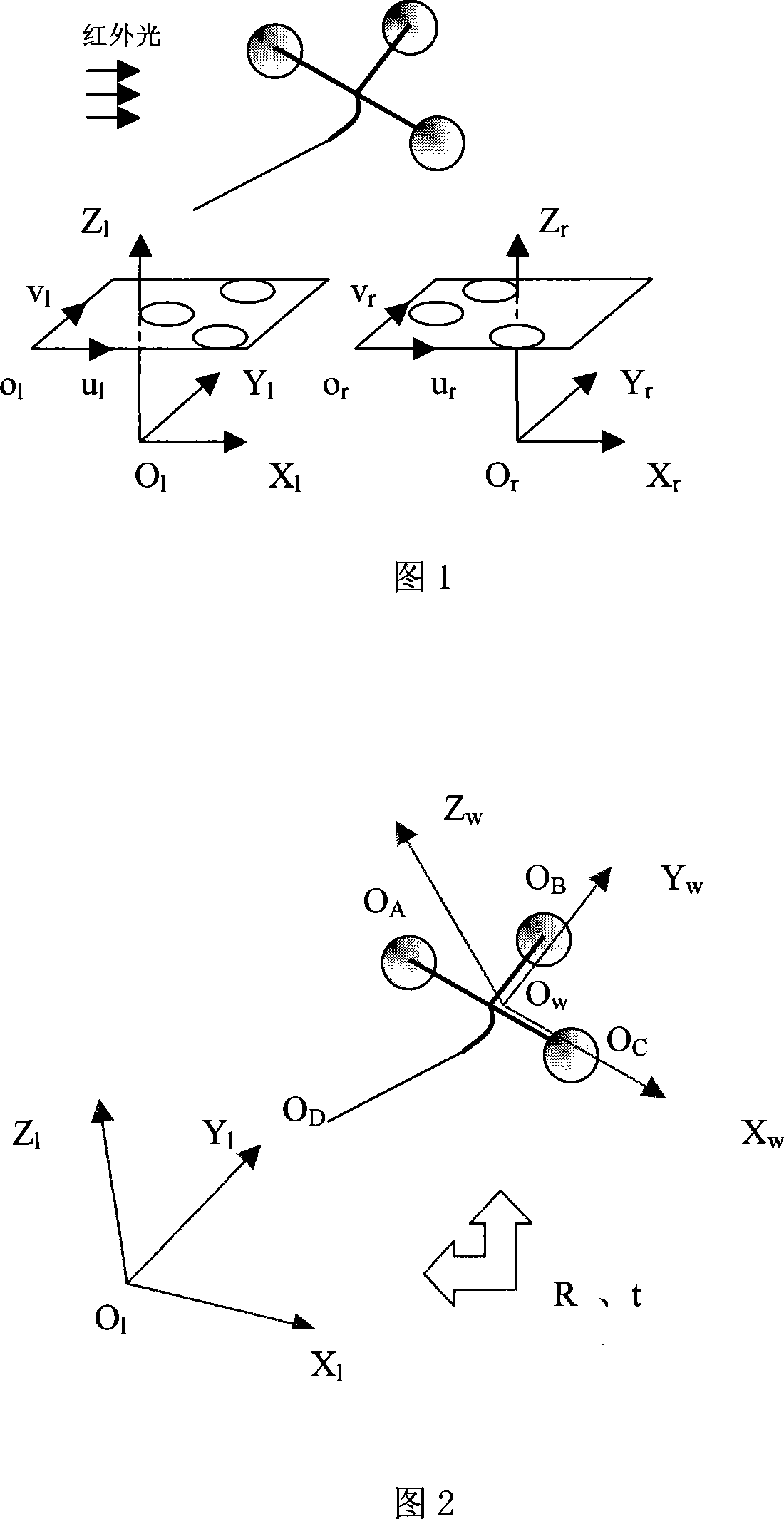
[0022] FIG. 1 is a schematic diagram of the positioning method of the present invention, in which a binocular stereo vision system with any configuration is shown. o l x l Y l Z l and O r x r Y r Z r are the left and right camera coordinate systems, o l u l v l and o r u r v r are the left and right image coordinate systems in pixels, respectively. A navigation bracket equipped with three infrared reflective balls that are not on the same straight line is placed within the common field of view of the left and right cameras. Use the left and right cameras to shoot the navigation bracket at the same time. At this time, three ellipses are obtained on the left and right images respectively, which are the projections of the three infrare...


PUM


Abstract

The present invention relates to an operative instrument positioning method by adopting infrared reflecting ball as marker point. Said method includes the following steps: respectively defining internal parameter and first order radial distortion parameter of left and right cameras; calculating rotation matrix and translation vector characterizing relative position relationship of left and right two cameras; utilizing infrared light source to irradiate guide frame in which three infrared reflecting balls are mounted; shooting to obtain left and right two images containing elliptical images of infrared reflecting balls and making distortion correction; combining elliptical images of left and right image planes which are undergone the process of distortion correction and directly and linearly calculating projection points of three infrared reflecting ball cores; matching said projection points and reconstructing ball core coordinates of three infrared reflecting balls; finally utilizing coordinate conversion to obtain the coordinate of tip end working portion of operative instrument.

Description

technical field [0001] The invention relates to a surgical instrument positioning method using an infrared reflective ball as a mark point, which can be applied to a surgical instrument tracking and positioning system in a surgical navigator, and can be extended to all optical positioning systems that use an infrared reflective ball as a mark point. The invention belongs to the field of advanced medical equipment and technology. Background technique [0002] So far, surgical operations mainly rely on doctors to judge the location of the lesion with the naked eye, so as to perform operations such as surgical resection. The disadvantage of this method is that the surgical opening is large, the bleeding is much, and the postoperative recovery time is long. With the development of computer imaging technology, virtual reality technology and computer vision theory, people pay more and more attention to Surgical Navigation System. The surgical navigation system can provide doctor...

Claims


Application Information

Patent Timeline
IPC IPC(8): A61B5/06A61B17/00G06T5/00
Inventor 郑银强刘允才
Owner SHANGHAI JIAO TONG UNIV
Why Eureka
Try Eureka