
Water purifying apparatus

A technology for water purifiers and water production pipes, applied in chemical instruments and methods, filtration separation, semi-permeable membrane separation, etc., can solve the problem that the filter element cannot be taken out for cleaning

Inactive Publication Date: 2008-01-09
NEW CENTURY MEMBRANE TECH
View PDF0 Cites 12 Cited by
  • Summary
  • Abstract
  • Description
  • Claims
  • Application Information

AI Technical Summary

Problems solved by technology

[0008] Therefore, the purpose of the present invention is to provide a water purifier to solve the problem that the filter element of the previous water purifier cannot be taken out for cleaning, but can only be cleaned with special agents or directly replaced and discarded.

Method used


Image

  • Water purifying apparatus
  • Water purifying apparatus
  • Water purifying apparatus

Examples


Embodiment Construction

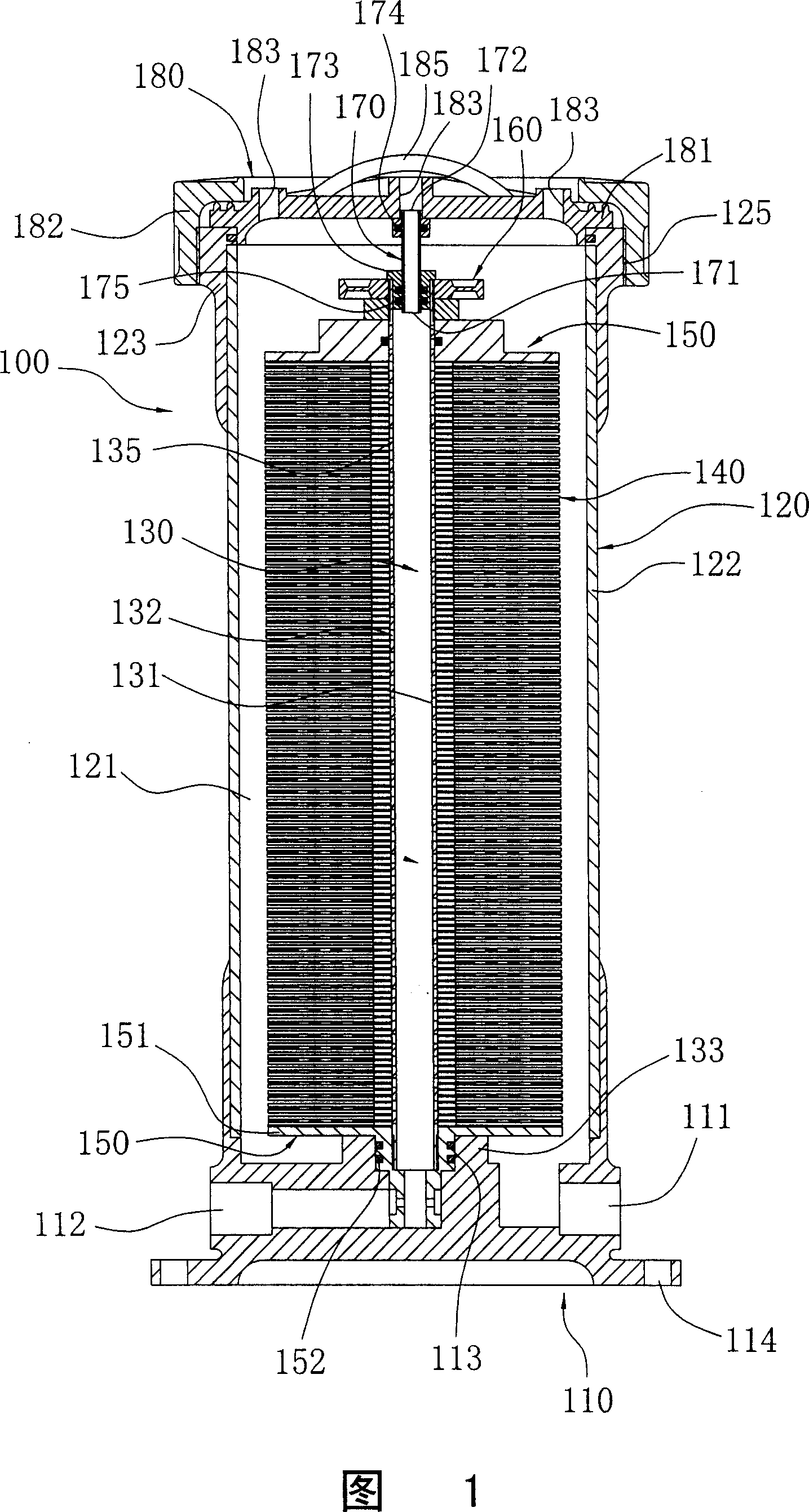
[0058] Please refer to FIG. 1 , which shows a combined cross-sectional view according to a preferred embodiment of the present invention.

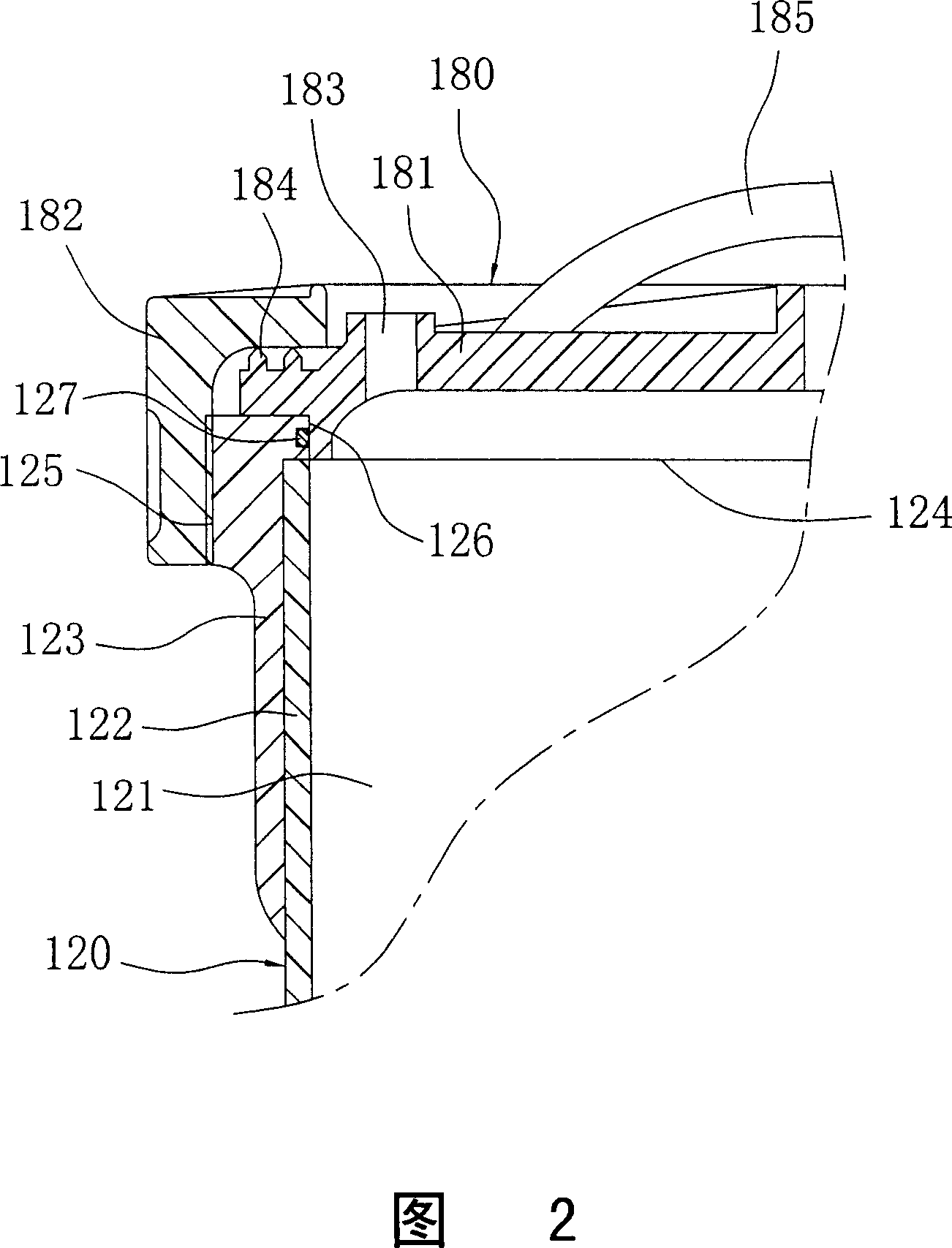
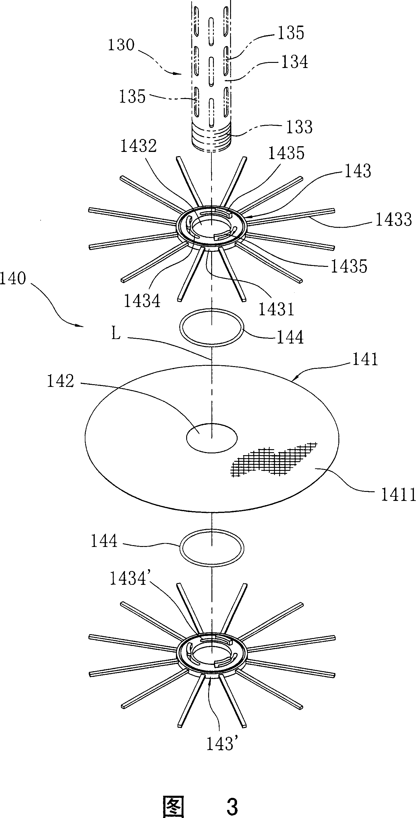
[0059] The water purifier 100 can be installed at the water inlet end of the water storage tower (pool), and includes a shell base 110, an outer shell 120, a water production pipe 130, a plurality of filter units 140, two pressure plates 150, a pull ring 160 , an exhaust pipe 170 , and a cover 180 .

[0060] The shell seat 110 is a stepped seat with an open top, and has a water inlet hole 111, a water outlet hole 112, a central hole 113 set in the center and perpendicular to the water outlet hole 112, and a plurality of holes located at the bottom periphery. The positioning hole 114, the water inlet hole 111 is for communicating with the raw water delivery pipeline, and a valve (not shown) can be used to open and close the delivery of raw water, while the central hole 113 is communicated with the water outlet hole 112.

[0061] The outer ...


PUM


Abstract

The water purifier includes one seat, one casing on the seat, one detachable water-producing pipe inside the casing, several detachable laminated filter units around the water producing pipe, and one detachable top cover. Each of the filter units has one flat filter membrane bag, one central hole and clamps for water tightly connection to the adjacent filter membrane bag. There are gaps between adjacent filter membrane bags for direct cleaning before being reused.

Description

technical field [0001] The invention relates to a water purifying device, and in particular to a water purifier which can detach and clean the filter membrane. Background technique [0002] The current tap water is to add chlorine to the raw water to achieve disinfection and sterilization. However, after the tap water is distributed through long and old pipelines, various pollutions may still take advantage of the gap, resulting in poor quality of the released water. Therefore, each Class water purifier just arises at the historic moment, and common water purifier mainly comprises a housing that has a bottom opening, a filter element that is detachably installed in this housing, a bottom cover that is installed in this housing bottom opening , and a one-way valve installed on the bottom cover, wherein the filter element is mainly made of fiber materials such as cotton yarn or non-woven fabric in a wave-folded shape, and has a central through hole, and the bottom cover has a ...

Claims


Application Information

Patent Timeline
Patent Type & Authority Applications(China)
IPC IPC(8): B01D63/00B01D25/02
Inventor 郭瑜珊
Owner NEW CENTURY MEMBRANE TECH
Learn More