
Cell management method and apparatus

一种管理方法、小区的技术,应用在多个站之间的通信、网络规划、电气元件等方向,能够解决不能非工作小区分配保护频率、可用频率带宽有限制、不能保证工作小区呼叫等问题,达到改进可靠性和通信质量、防止呼叫丢失事件的效果

Inactive Publication Date: 2008-01-09
FUJITSU LTD
View PDF2 Cites 0 Cited by
  • Summary
  • Abstract
  • Description
  • Claims
  • Application Information

AI Technical Summary

Problems solved by technology

[0025] In the prior art examples described above, although call loss events can be prevented by utilizing the guard frequency bandwidth, the guard frequency cannot always be assigned to the non-operating cell because there is a limitation on the available frequency bandwidth in the wireless communication system (for example, due to Restrictions arising from allocation of frequency bandwidth among companies operating similar wireless communication systems, and restrictions due to frequency bandwidth used by other communication equipment, systems, etc.)
Therefore, in the prior art example described above, there is a problem that, when there is a limitation on the available frequency bandwidth, in the case where it is not possible to prepare enough non-operating cells to which the guard frequency bandwidth is allocated, when the cell usage rate increases, Call loss can occur due to the inability to guarantee the number of active cells for the mobile station requesting the call connection

Method used


Image

  • Cell management method and apparatus
  • Cell management method and apparatus
  • Cell management method and apparatus

Examples


Embodiment approach

[0108] Implementation of I.2.A.c cell utilization rate management table: Figure 6B

[0109] As shown in Figure 6B, in the cell utilization rate management table TBL1, in addition to the cell ID and the cell utilization rate corresponding to the cell ID, there are also radio network control equipment numbers (RNC numbers), base station numbers, and the number used to uniquely identify the coverage area. The directional sector number of each cell CL in the AR, the working status of each cell CL (working / non-working), the number of adjacent wireless network control equipment (adjacent RNC number), when the cell utilization rate is in a high load state A cell ID of a cell CL that becomes a cell addition candidate and a cell deletion candidate, and when the cell usage rate is in a low load state, becomes a cell addition candidate and a cell deletion candidate.

[0110] Taking the cell CL_002 as an example, the cell CL_002 represents the cell with the sector number "002", which is...

Embodiment approach 1

[0133] II.1. Implementation of Add / Delete Target Cell Determination Process [1]: Figures 11A, 11B and 12

[0134] This embodiment executes the cell addition / deletion candidate data registration processing example and the cell addition / deletion instruction data registration processing example according to the state of the cell usage rate.

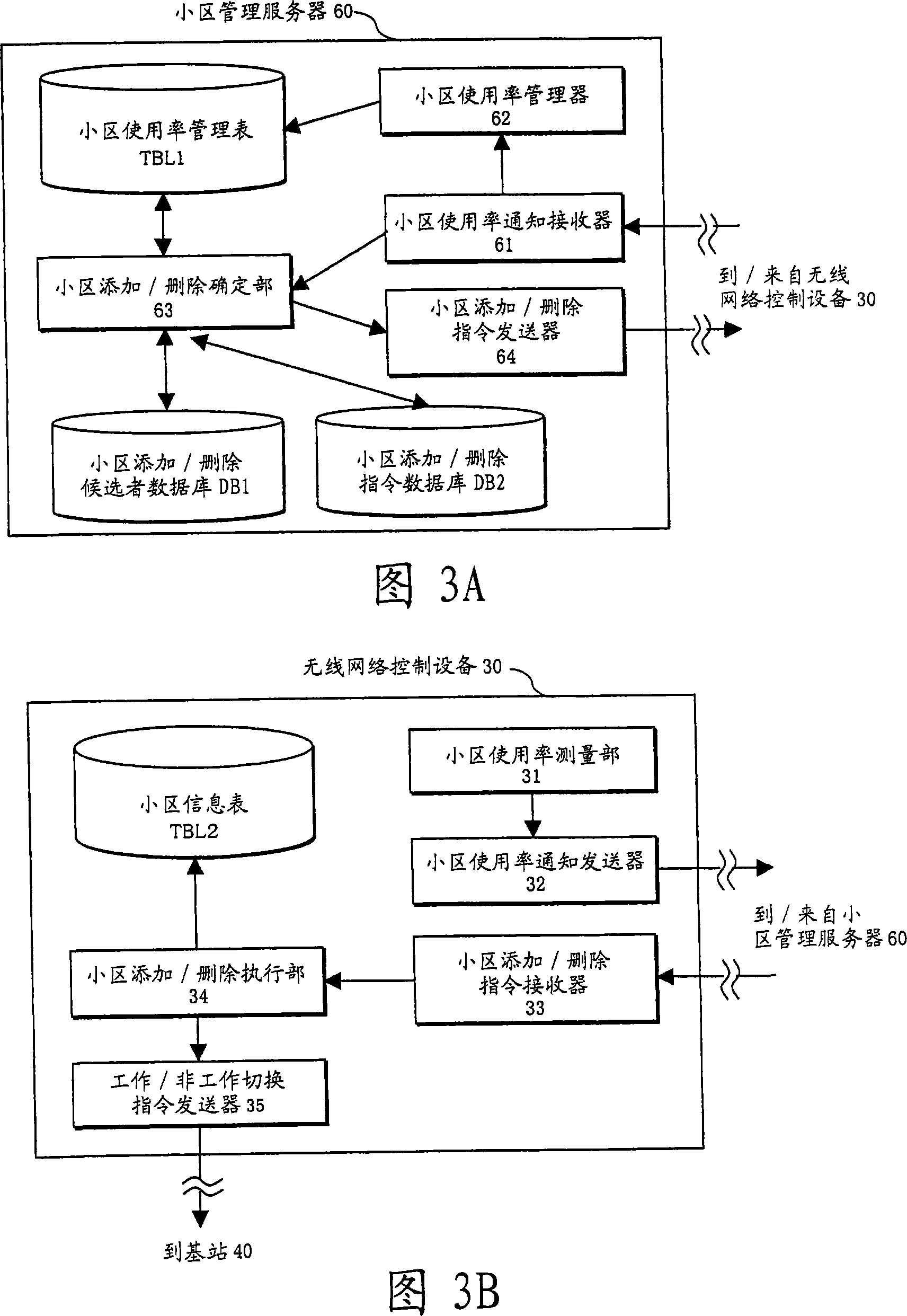
[0135] II.1.A. Cell Addition / Deletion Candidate Data Registration Processing Example: FIGS. 11A and 11B

[0136] As shown in FIG. 11A , the cell addition / deletion determination section 63 sequentially inquires about all cells CL in the wireless communication system 1 (that is, records corresponding to all cell IDs in the cell utilization rate management table TBL1 shown in FIG. 6B ) ( at step S10).

[0137] When it is determined that the cell utilization rate of the inquired cell CL is higher than the high load state threshold Th_H (at step S11), the cell addition / deletion determining section 63 inquires the high load state correspondi...

Embodiment approach 2

[0171] II.2. Embodiment of Add / Delete Target Cell Determination Process [2]: Figures 13 to 15

[0172] In the present embodiment, cell addition / deletion candidate data registration and cell addition / deletion instruction data registration are performed based on the history and forecast information of cells.

[0173] II.2.A. Cell add / delete command data registration processing embodiment: Figures 13 and 14

[0174] In addition to the processing flow shown in Figure 12, the cell add / delete command data registration shown in Figure 13 also includes the work / non-work switching history and forecast information update (at steps S33 to S38) surrounded by dotted lines in Figure 13 ; however, the processing at steps S33 to S35 is the same as the processing at steps S36 to S38). In the cell utilization rate management table TBL1 shown in FIG. 14, "working / non-working switching history record" and "forecast information" are added to the information items shown in FIG. 6B.

[0175] T...


PUM


Abstract

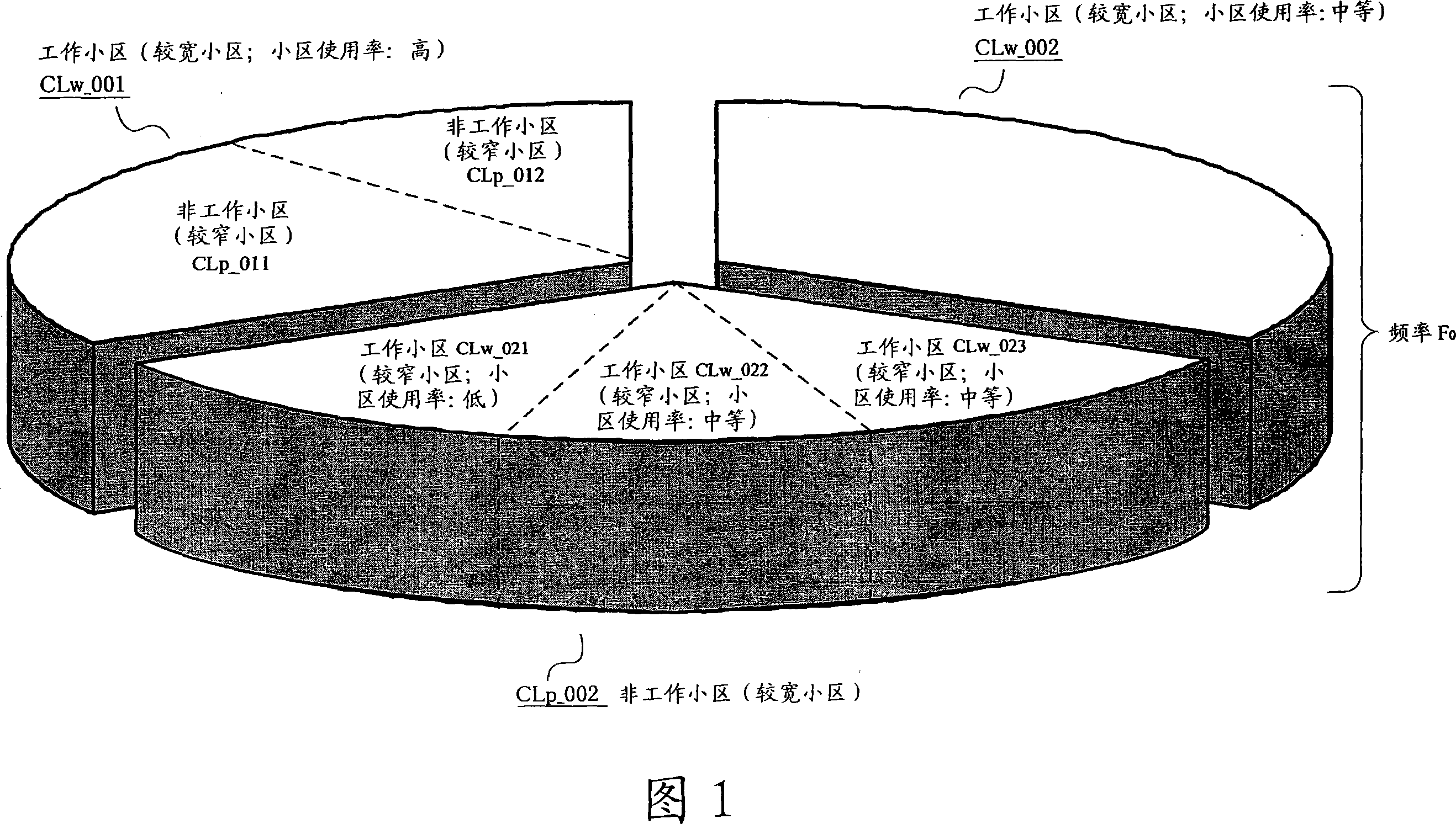
In a cell management method and apparatus which can prevent a call loss generated in association with an increase of cell usage rate independent of a protection frequency bandwidth, cell usage rates of operating cells (at frequency Fo) are acquired. Narrower nonoperating cells (at frequency Fo) of the operating cell in which the cell usage rate indicates a high-load state are rendered an addition candidate and the operating cell is rendered a deletion candidate. A broader nonoperating cell (at frequency Fo) of the operating cell in which the cell usage rate indicates a low-load state is rendered an addition candidate, and the operating cell and other narrower operating cells belonging to the nonoperating cell are rendered deletion candidate. From among the nonoperating cells that are the addition candidate and the operating cells that are the deletion cell(s) and an operating cell(s) to be switched over to a nonoperating cell(s) is determined.

Description

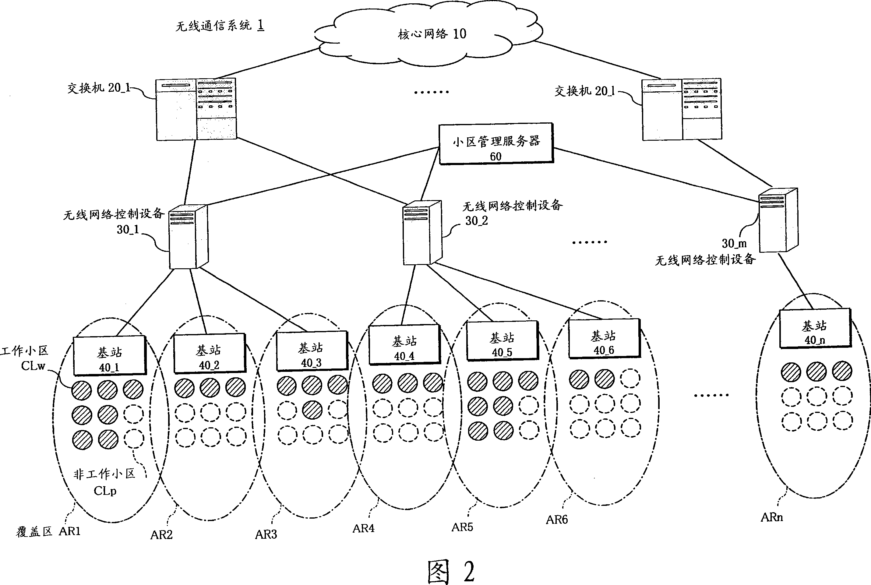
technical field [0001] The present invention relates to a cell management method and device, in particular to a cell management method and device for switching a cell to a working / non-working (active / inactive) state based on the cell usage rate and the like. Background technique [0002] A prior art example of the above-mentioned cell management technology will now be described with reference to FIGS. 18 to 21A and 21B. [0003] Wireless communication system 1 shown in FIG. Wireless network control devices 30_1 to 30_m (sometimes denoted by reference numeral 30 below) and “n” base stations 40_1 to 40_n (sometimes denoted by reference numeral 40 below) managed by these wireless network control devices 30 are composed. [0004] As shown in FIG. 19 , communication of voice data and packet data is performed in the wireless communication system 1 . Each mobile station 50_1 to 50_k (hereinafter sometimes indicated by reference numeral 50 ) located in the coverage area AR1 to ARn...

Claims


Application Information

Patent Timeline
Patent Type & Authority Applications(China)
IPC IPC(8): H04Q7/38H04B7/26H04W16/02H04W16/04H04W16/24H04W16/32
CPCH04W16/04H04W16/32H04W16/24
Inventor 高田竜彦福泽洋司宫垣努大迫周平坂本孝介谷口德明
Owner FUJITSU LTD
Learn More