Micro modular pasting header for high speed fully automatic chip machine

A fully automatic, placement head technology, applied in the direction of assembling printed circuits, electrical components, electrical components, etc. with electrical components, can solve problems such as limiting the popularization of technology, achieve high control accuracy, small size, easy system integration and system integration optimized effect

Inactive Publication Date: 2008-01-09
BEIHANG UNIV
View PDF0 Cites 20 Cited by
  • Summary
  • Abstract
  • Description
  • Claims
  • Application Information

AI Technical Summary

Problems solved by technology

Due to the shortcomings of the above-mentioned several types of placement head systems, their development and the popularization of related technologies are limited to a certain extent.

Method used


Image

  • Micro modular pasting header for high speed fully automatic chip machine
  • Micro modular pasting header for high speed fully automatic chip machine
  • Micro modular pasting header for high speed fully automatic chip machine

Examples


Embodiment Construction

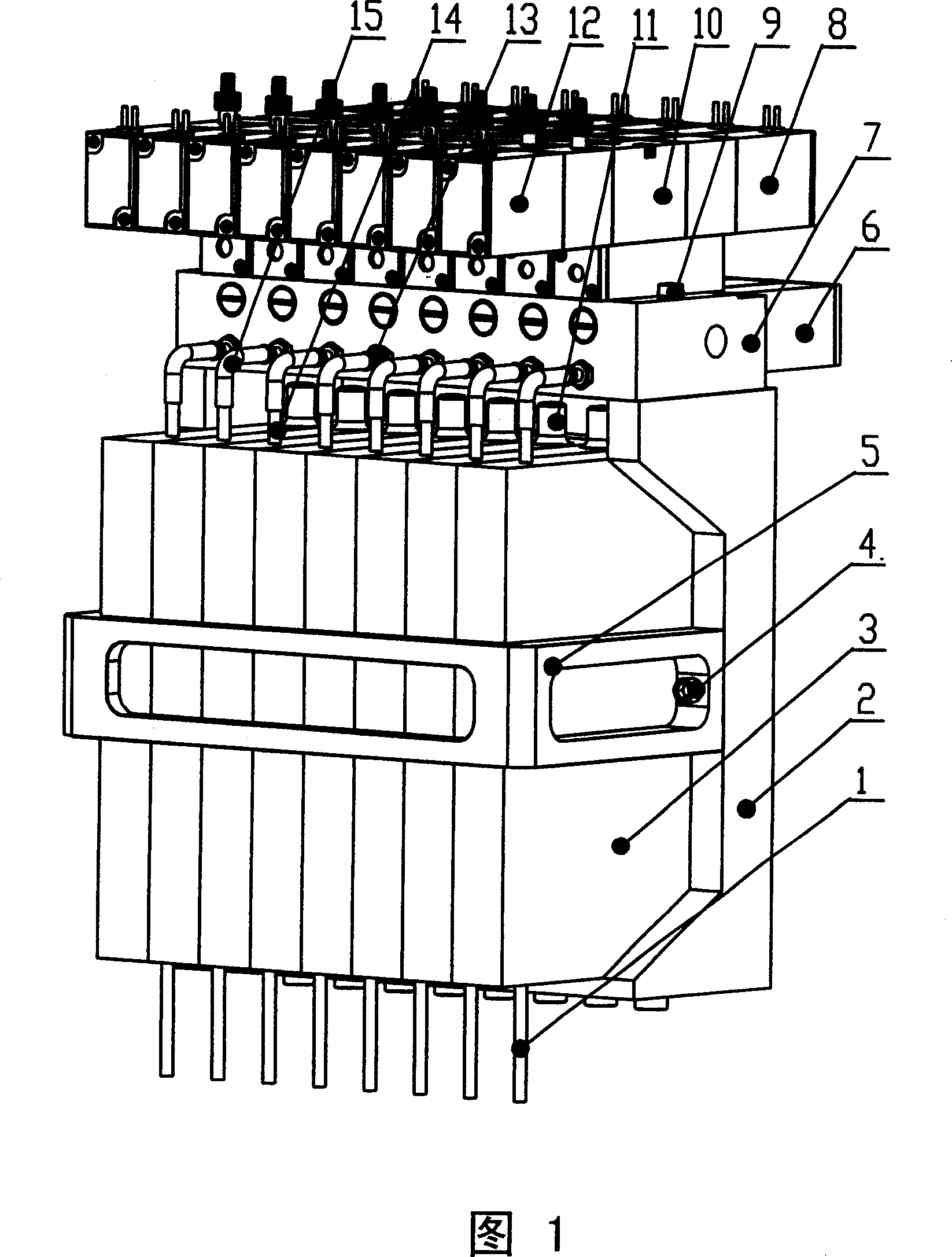
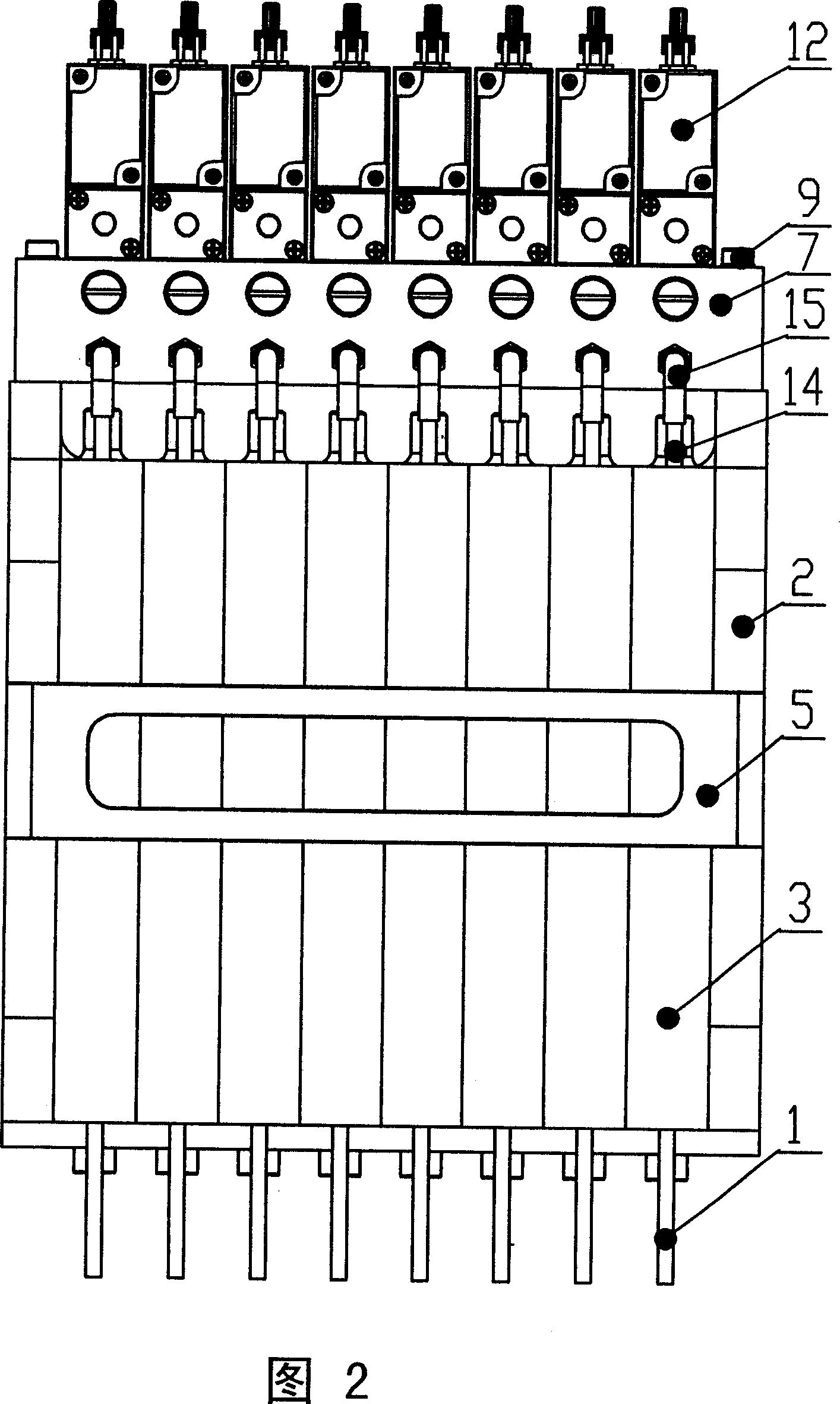
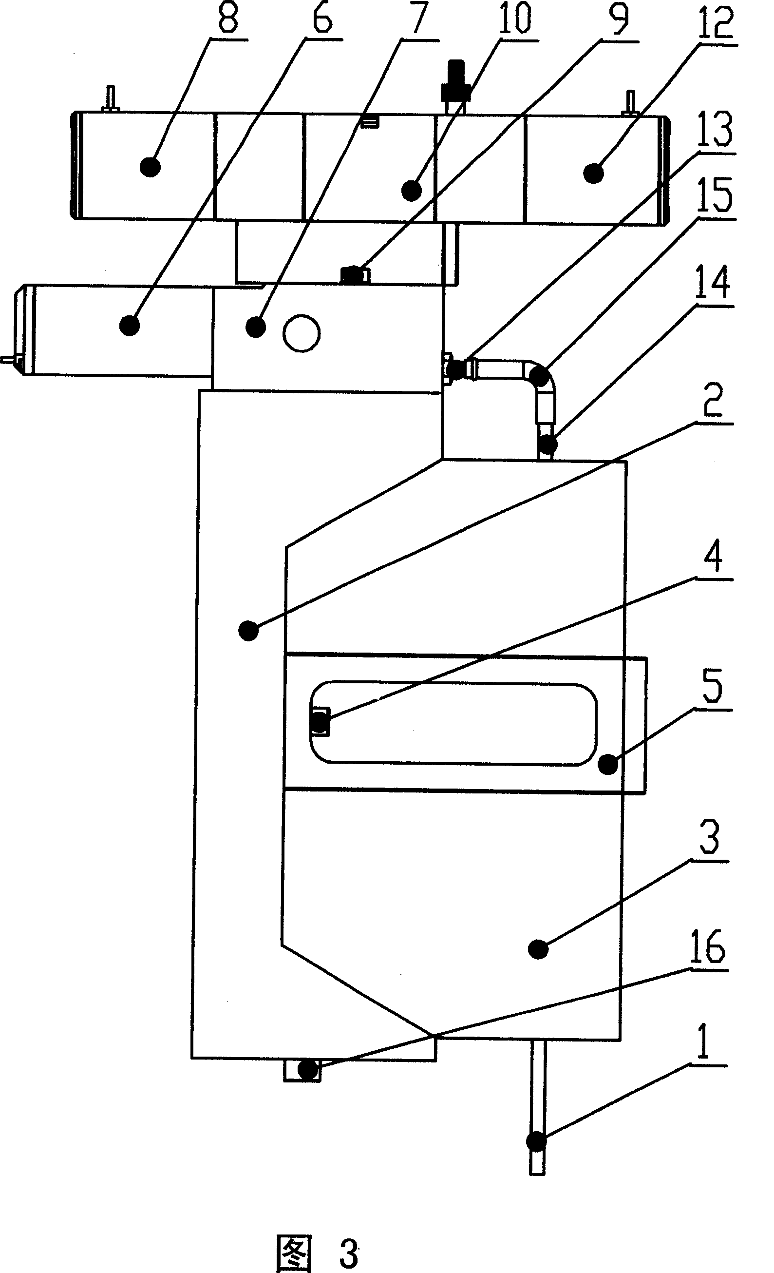
[0027] The miniature modular placement head of the high-speed automatic placement machine includes a fixed frame, a placement module and a vacuum module, and is characterized by:

[0028] As shown in Figure 1, the fixed frame is a dustpan-shaped frame composed of the main frame 2 and the sub-frame 5, and the bottom of the dustpan-shaped frame has a horizontal positioning surface and a vertical positioning surface; The shape is a cuboid, and the bottom and side surfaces of the cuboid mounting module are positioning surfaces, which match with the positioning surfaces of the fixed frame; the vacuum module is located directly above the fixed frame.

[0029] As shown in Fig. 1, Fig. 3, Fig. 5, described fixed frame comprises main frame 2 and subframe 5, and main frame 2 has baffle plate on three sides, and upper end opening is connected for cable wire, and main frame 2 has two backs. There are threaded holes for countersunk heads, a row of threaded holes at the lower end, threaded ...


PUM


Abstract

The invention comprises a securing frame, a chip placement head and chip placement module and a vacuum module. Said securing frame is a dustpan-like frame composed of a main frame and a slave frame; the chip placement module is a cuboid; the vacuum module is located above the securing frame; based on the securing frame, the chip placement module and vacuum module are secured on the securing frame; during operation, in each moment only one surface-mounted component acts; each surface-mounted component acts sequentially; the vacuum system fits the hollow axle action to control the vacuum source to generate or destroy the press control in order to absorbing or place the chip by the hollow axle.

Description

(1) Technical field [0001] The invention relates to the field of SMT (Surface Mount Technology, surface mount technology) placement machines, in particular to the technical field of an electronic surface mount placement machine and its mounting head assembly. (2) Background technology [0002] Surface mount technology (SMT) originated in the late 1950s, with the invention of semiconductor integrated circuits, thick and thin film hybrid integrated circuits. Due to the hard texture of the ceramic substrate, it is not convenient to punch holes for component insertion, and chip components are used, so chip capacitors and chip resistors appear, and active components use bare chips, wire bonding or flip chips, etc. form to assemble. After entering the 1970s, the application of hybrid integrated circuits began to expand from the military field to the industrial and civilian fields, and the production scale expanded rapidly. At the end of the 1970s and the beginning of the 1980s, ...

Claims


Application Information

Patent Timeline
Patent Type & Authority Applications(China)
IPC IPC(8): H05K13/04H05K3/32
Inventor 刘强吴文镜郑妍袁松梅
Owner BEIHANG UNIV
Why Eureka
Try Eureka