Electric direct-acting actuator and electric brake device

一种电动式、促动器的技术,应用在机电装置、传动装置、电动组件等方向,能够解决齿轮易损伤、妨害电动式直动促动器紧凑设计、不能充分确保直线运动行程等问题,达到紧凑设计、大增力功能的效果

Inactive Publication Date: 2008-01-09
NTN CORP
View PDF2 Cites 21 Cited by
  • Summary
  • Abstract
  • Description
  • Claims
  • Application Information

AI Technical Summary

Problems solved by technology

In addition, in the case of the ball ramp mechanism, if the inclination angle of the cam surface is reduced, the linear motion stroke cannot be sufficiently ensured.
[0008] Therefore, in the electric direct-acting actuators employing these motion conversion mechanisms, the reduction mechanism as described above is separately installed to increase the driving force. However, incorporating a gear reduction mechanism such as a planetary gear reduction mechanism not only hinders The compact design of the electric linear actuator, and because the gear reduction mechanism meshes the gears with each other with a small contact area, there is a problem in the structure installed on the part that receives the vibration from the road surface like the electric brake device. The problem of easy damage to gears

Method used


Image

  • Electric direct-acting actuator and electric brake device
  • Electric direct-acting actuator and electric brake device
  • Electric direct-acting actuator and electric brake device

Examples


Embodiment Construction

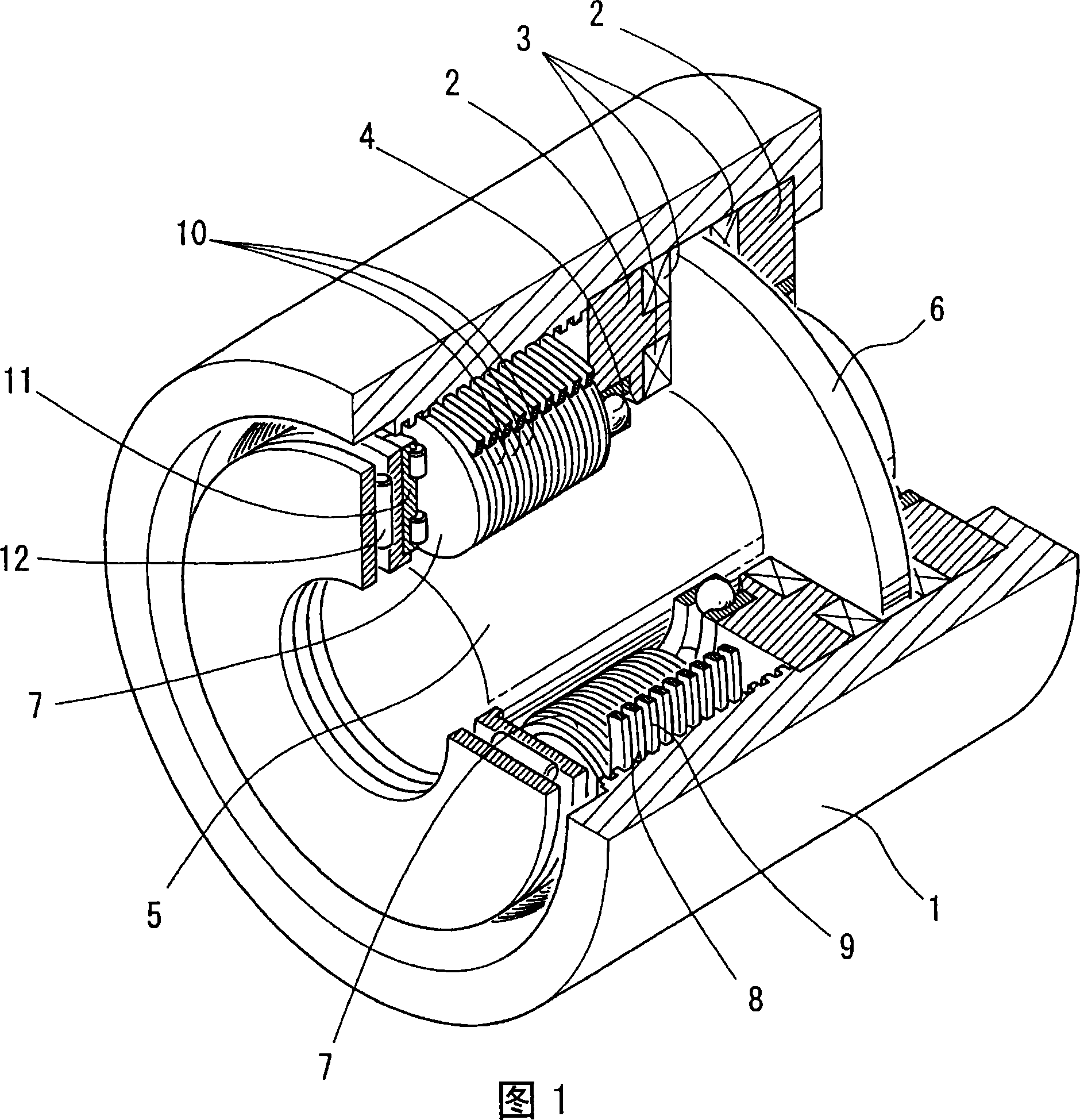
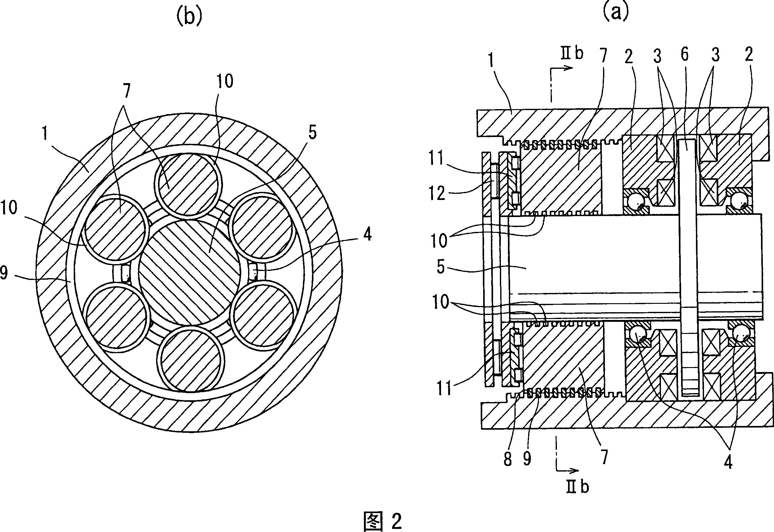
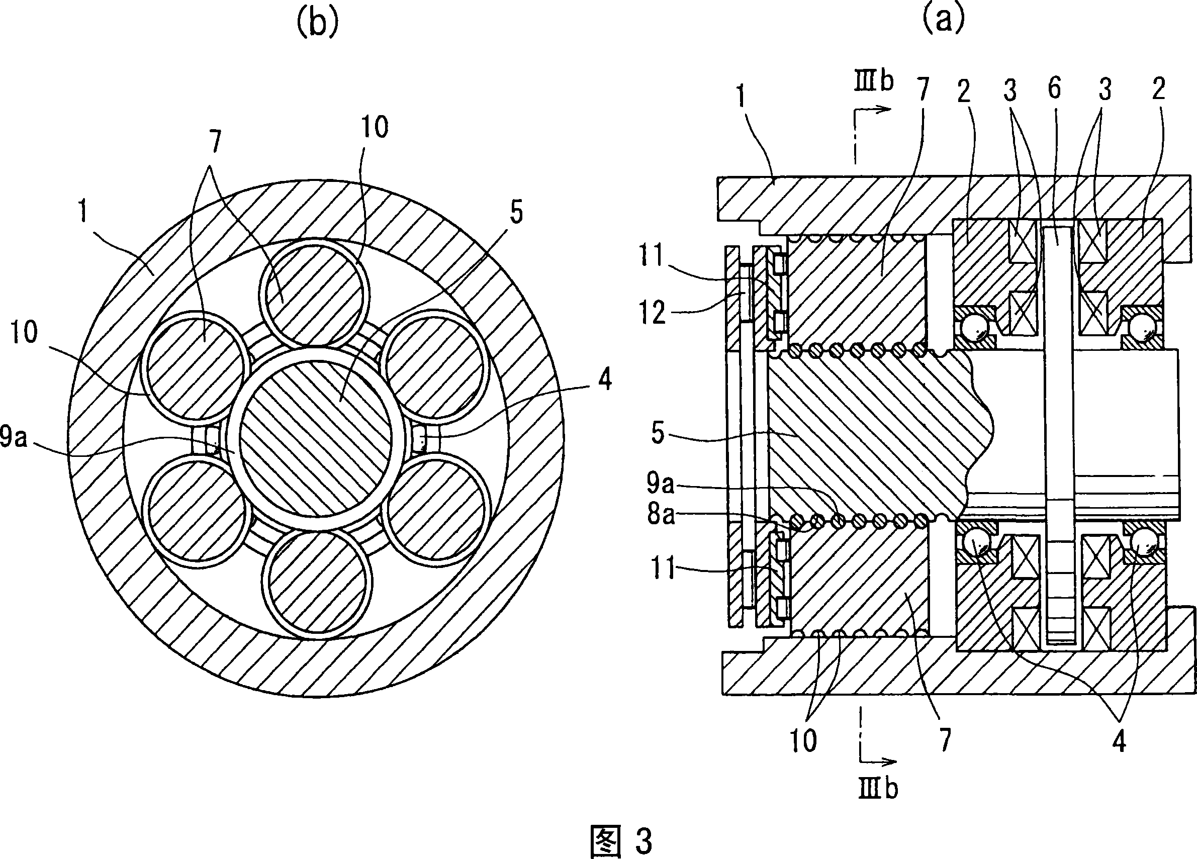
[0028] Hereinafter, embodiments of the present invention will be described with reference to the drawings. Fig. 1 and Fig. 2(a), (b) show an electric linear motion actuator according to a first embodiment. In this electric linear actuator, a pair of stator cores 2 embedded in one end of an outer ring member 1 are fixed to axially oppose coils 3 of a multi-pole electric motor, and a rotor shaft 5 is supported by a ball bearing 4. On the stator core 2, a rotor 6 mounted on a rotor shaft 5 rotates between opposing stators. In addition, between the inner diameter surface on the other end side of the outer ring member 1 and the outer diameter surface of the rotor shaft 5, a plurality of planetary rollers 7 are interposed with a negative gap, and these planetary rollers 7 surround the rotor as the rotor shaft 5 rotates. The axis 5 revolves while rotating. The outer diameter surface of the planetary rollers 7, the inner diameter surface of the outer ring member 1 and the outer diam...


PUM


Abstract

An electric direct-acting actuator capable of securing a large boosting function without assembling a separate speed reduction mechanism therein and an electric brake device. A plurality of planetary rollers (7) are interposed between the outer diameter surface of the rotor shaft (5) of an electric motor and the inner diameter surface of an outer ring member (1) fixed to the outer diameter side of the rotor shaft (5). Peripheral grooves (10) in which spiral projected lines formed of line members (9) peripherally fixed to spiral grooves (8) formed in the inner diameter surface of the outer ring member (1) are fitted are formed in the outer diameter surfaces of the planetary rollers (7) at the same pitch as that of the spiral projected lines so that the planetary rollers (7) can be revolved around the rotor shaft (5) while rotating about its axis according to the rotation of the rotor shaft (5). By converting the rotating motion of the rotor shaft (5) into the linear motion of the planetary rollers (7), the large boosting function can be secured without assembling the separate speed reduction mechanism therein.

Description

technical field [0001] The present invention relates to an electric linear actuator that converts the rotary motion of an electric motor into linear motion to linearly drive a driven object, and an electric linear actuator that presses a brake member against a brake member Electric braking device. Background technique [0002] In the electric linear actuator that converts the rotary motion of the electric motor into linear motion to linearly drive the driven object, a ball screw mechanism or a ball ramp mechanism is often used as the motion conversion mechanism. An electric motor obtains a large linear driving force, and is often incorporated in a gear reduction mechanism such as a planetary gear reduction mechanism (for example, refer to Patent Document 1). [0003] On the other hand, a hydraulic structure is often used as a vehicle brake device. However, in recent years, with the introduction of advanced brake control such as ABS (Antilock Brake System), it can be perform...

Claims


Application Information

Patent Timeline
Patent Type & Authority Applications(China)
IPC IPC(8): F16H25/20F16D65/18H02K7/06
CPCH02K7/06F16D2125/405F16D65/18F16D2121/24F16H25/2252F16H25/2427H02K7/102H02K21/24Y10T74/18568
Inventor 中关嗣人
Owner NTN CORP
Why Eureka
Try Eureka