
Numerically controlled cutting control device and numerically controlled cutting control method

A technology of a control device and a control method, which is applied in the field of numerical control, can solve the problems of insufficient precision, low efficiency, large geometric size of assembly parts, etc., and achieves the effects of accurate marking, reliable marking and fast speed.

Active Publication Date: 2008-01-16
WUCHANG SHIPBUILDING IND +1
View PDF0 Cites 45 Cited by
  • Summary
  • Abstract
  • Description
  • Claims
  • Application Information

AI Technical Summary

Problems solved by technology

[0002] After the existing CNC cutting machine is blanked, the worker generally writes the part identification on the part with paint according to the nesting diagram of the blanked material. The position correspondence determines the part identification, so when there are many parts on a nesting board, the correspondence between the parts is prone to errors and low efficiency; at the same time, the assembly line needs to be drawn before the parts are assembled to determine the structural assembly position. Due to the large geometric size of the assembly parts , the accuracy of the traditional powder thread elastic method cannot meet the requirements
Although some CNC cutting machines are equipped with powder spraying and scribing functions, the cost of use is high, and the scribing accuracy is difficult to meet the requirements, which cannot meet the production requirements.

Method used


Image

  • Numerically controlled cutting control device and numerically controlled cutting control method
  • Numerically controlled cutting control device and numerically controlled cutting control method
  • Numerically controlled cutting control device and numerically controlled cutting control method

Examples


Embodiment Construction

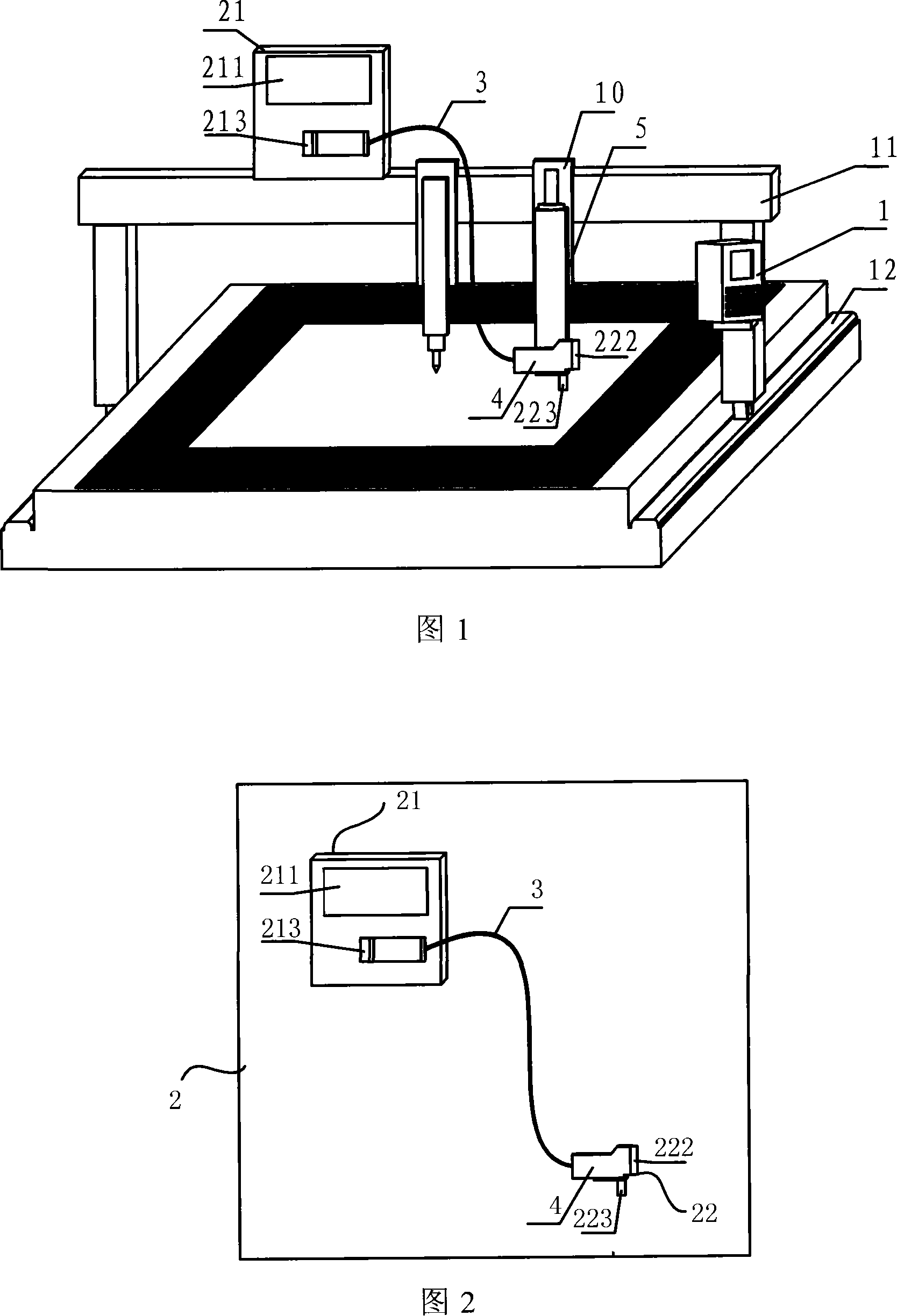
[0039] Fig. 1 is a schematic structural diagram of an embodiment of a numerically controlled cutting control device of the present invention. Fig. 2 is a schematic diagram of the mechanism of the embodiment of the laser marking machine of the present invention. Referring to Fig. 1 and Fig. 2, this numerical control cutting control device comprises: numerical control cutting machine 1, is used for moving its X-axis moving mechanism and Y-axis moving mechanism; Parallel interface connection, used to generate marking machine control files and cutting instruction files, and move the laser marking head to the target area through the X and Y axis moving mechanism of the CNC cutting machine according to the cutting instruction files, and then carry out according to the marking machine control files Automatically identify or underline. The CNC cutting machine used in this embodiment is a 6500*16000 Messer CNC cutting machine. On the basis of keeping the CNC cutting machine 1 unchang...


PUM


Abstract

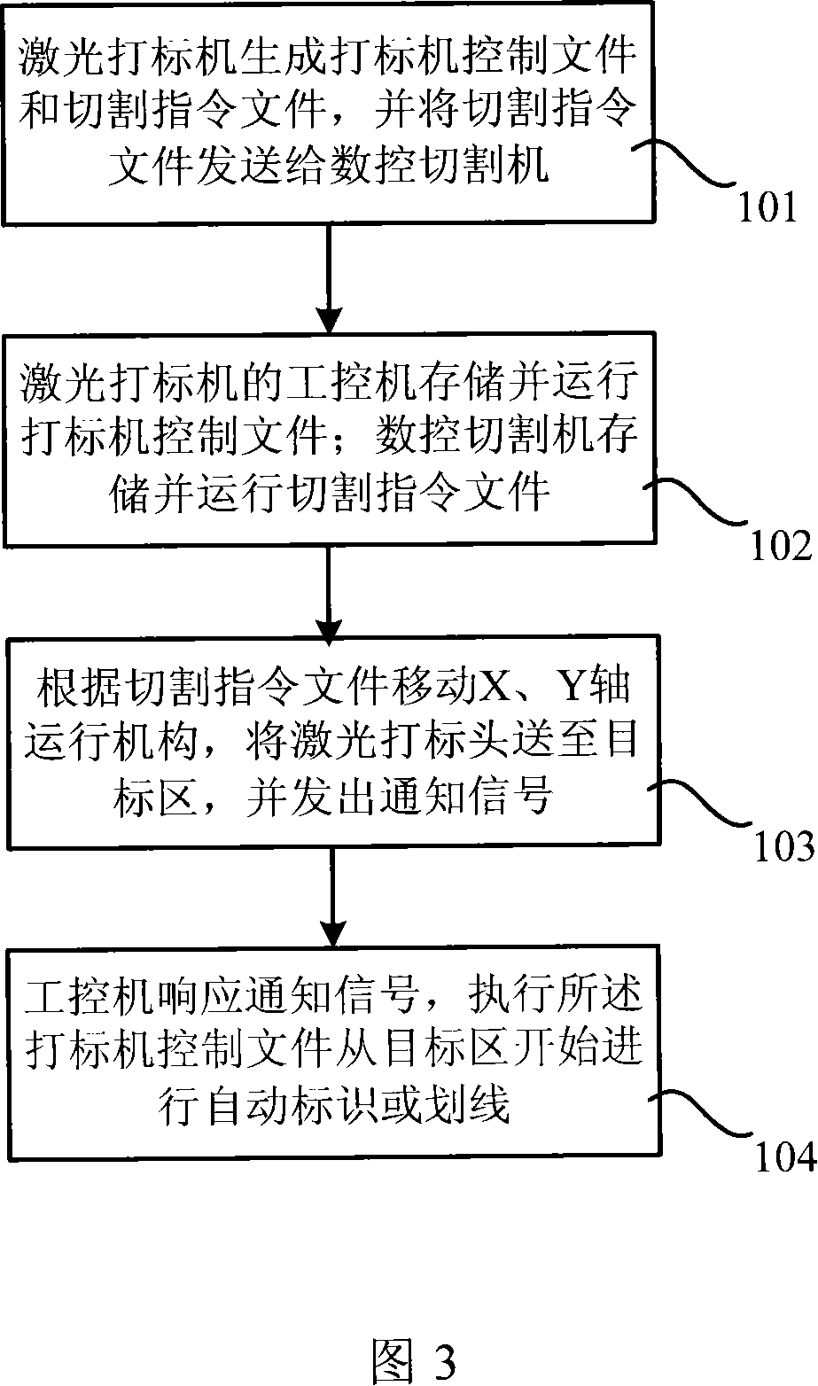
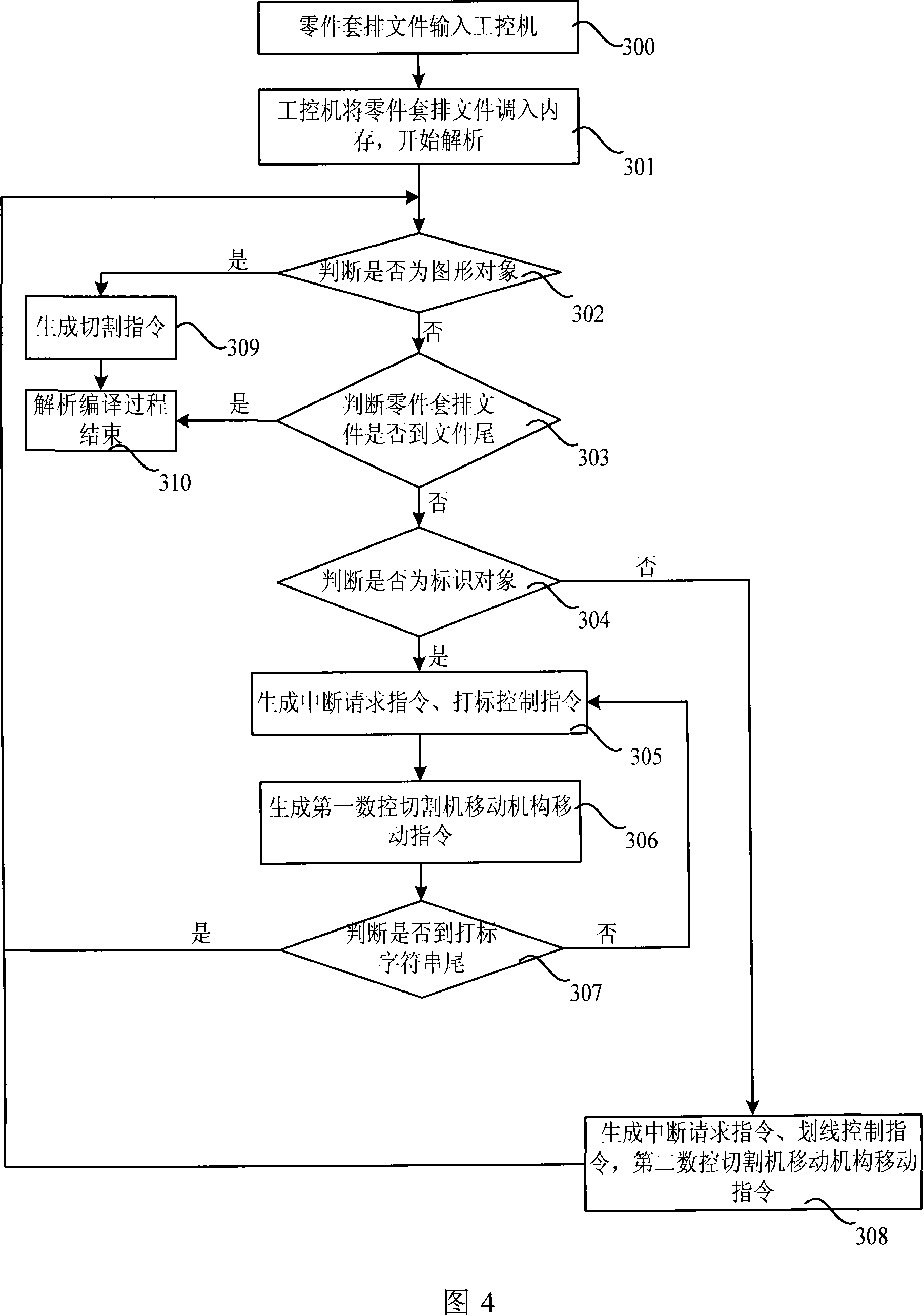
The invention relates to a digital control cutting control device, comprising a digital control cutting machine, which is used to drive moving mechanisms in X and Y axes of the digital control cutting machine; a laser marking machine, which is used to generate marking machine control files and cutting command files, and automatically marks and lines out according to the marking machine control files. The invention also relates to a digital control cutting control method, comprising a laser marking machine storing and operating marking machine controlling files. At the same time, the digital control cutting machine stores and operates the cutting command files. The digital control cutting machine drives the moving mechanisms in X and Y axes according to the cutting command files so as to drive a laser marking head to a target area, and sends out informing signals to the laser marking machine. The laser marking machine responds to the informing signals to automatically mark and line out from the garget area, implementing the marking machine control files. With advantages of reliable, visual and fast marking and accurate lining without damaging steel plates, the invention can automatically line out on parts.

Description

technical field [0001] The invention relates to the field of numerical control, in particular to a numerical control cutting control device for an integrated laser marking machine and a numerical control cutting control method for the numerical control cutting control device. Background technique [0002] After the existing CNC cutting machine is blanked, the worker generally writes the part identification on the part with paint according to the nesting diagram of the blanked material. The position correspondence determines the part identification, so when there are many parts on a nesting board, the correspondence between the parts is prone to errors and low efficiency; at the same time, the assembly line needs to be drawn before the parts are assembled to determine the structural assembly position. Due to the large geometric size of the assembly parts , the accuracy of the traditional powder thread elastic method cannot meet the requirements. Although some CNC cutting mac...

Claims


Application Information

Patent Timeline
Patent Type & Authority Applications(China)
IPC IPC(8): B23P23/00G05B19/18B41J3/407B41J2/47B41M5/24B23K7/00B23K26/04B23K26/362
Inventor 严俊徐爱忠彭祖洋黎明张志伟程颜江喻小会龚道龙罗飞龙叶青罗钰元易光纯朱学明王婕
Owner WUCHANG SHIPBUILDING IND
Learn More