Eureka AIR delivers breakthrough ideas for toughest innovation challenges, trusted by R&D personnel around the world.

Measurement method for photoelectric image gating light-valve shutter time calibration and device thereof

A measurement method and shutter technology, applied in the direction of measurement devices, optical instrument testing, machine/structural component testing, etc., can solve the problems of undiscovered measurement methods, small dynamic range, limited number of pulses, etc., and achieve low cost, The effect of good repeatability and convenient operation

Inactive Publication Date: 2008-01-30
SHENZHEN UNIV
View PDF0 Cites 8 Cited by
  • Summary
  • Abstract
  • Description
  • Claims
  • Application Information

AI Technical Summary

Problems solved by technology

Its disadvantages: First, the optical pulse train is decreasing. Since the dynamic range of the image changer tube camera is not large, the number of pulses that can detect the optical pulse train is limited, which directly affects the measurement accuracy; second, the etalon produces light. The pulse train needs to be expanded in space by optical methods, which will introduce errors and affect the measurement accuracy
[0003] After searching, no better measurement method for strobe shutter time calibration was found

Method used


Image

  • Measurement method for photoelectric image gating light-valve shutter time calibration and device thereof
  • Measurement method for photoelectric image gating light-valve shutter time calibration and device thereof
  • Measurement method for photoelectric image gating light-valve shutter time calibration and device thereof

Examples


example 1

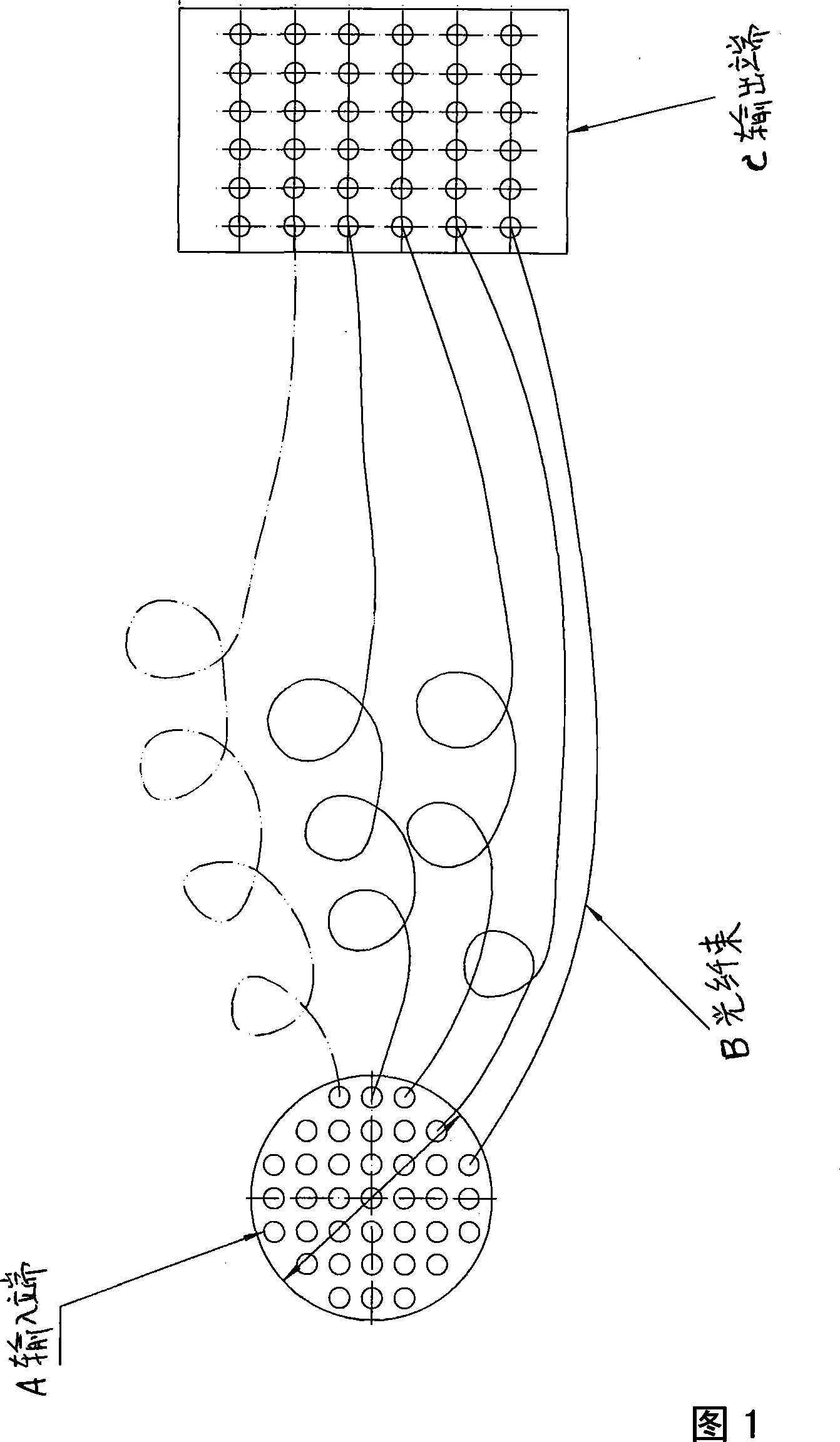
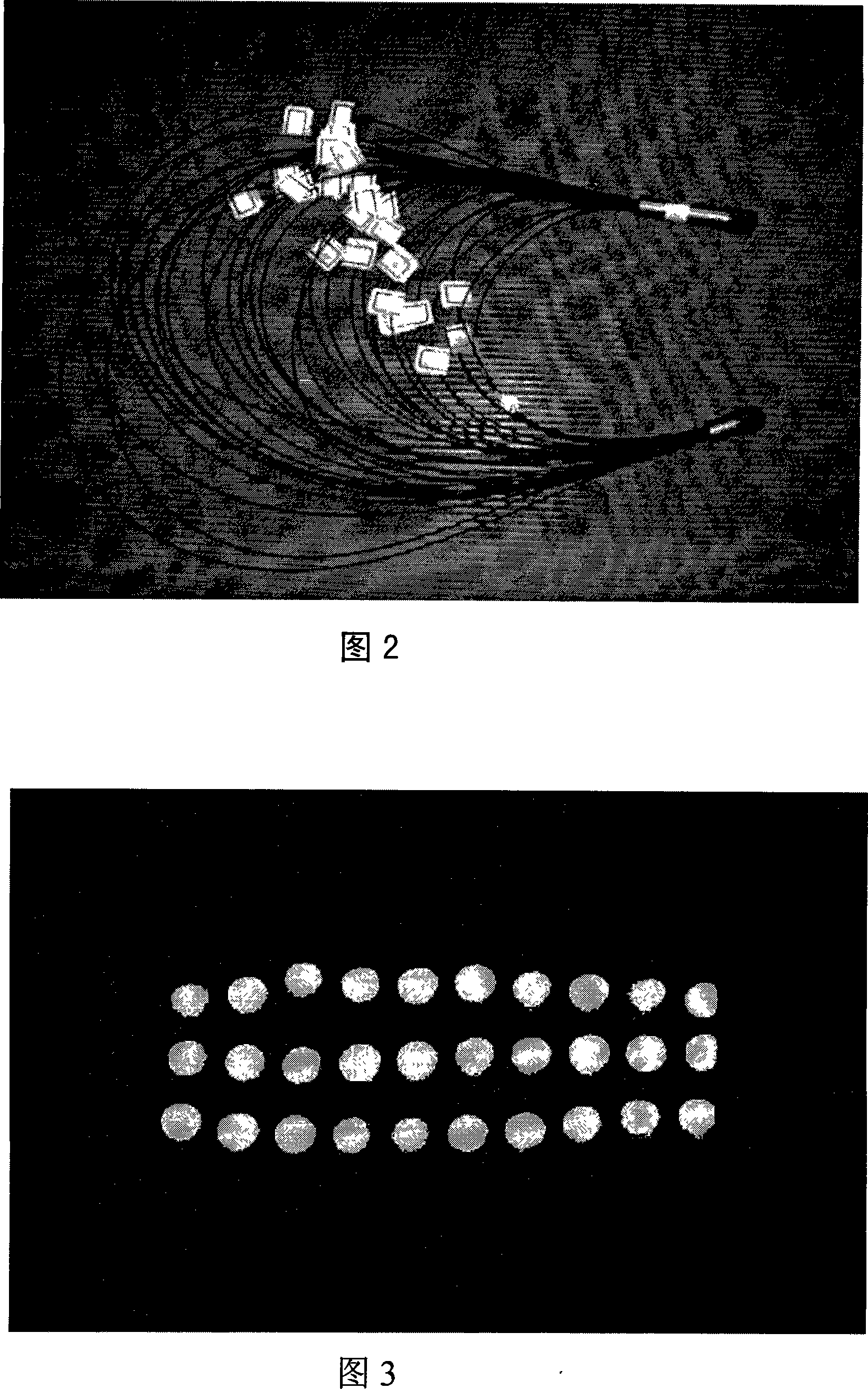
[0016] According to the above requirements, select a silica fiber with a diameter of 50 μm (the refractive index of the silica fiber is 1.5, and the speed of light is 2×10 10 cm / s) 30 pieces. If the length difference of the optical fiber is set as 15mm, the time interval is 75ps; the first optical fiber (the shortest one) is 300mm long, and from the second onwards, each fiber is 15mm longer than the previous one, and the thirtieth optical fiber (the longest one) is 300mm long. root) length 300+435=735mm; one end of the optical fiber head is randomly and evenly arranged in a circle of Φ3mm, fixed as the input end; the output end is arranged in a 3×10 array in the order of short and long, and the size is 5mm×1mm. There are 30 light spots of the ruler, as shown in Figure 3. In theory, it can measure the gate shutter time in the range of 75ps-2.18ns. In actual measurement, due to synchronization problems, it is inevitable that it will be lost, and the measurement range should be ...

example 2

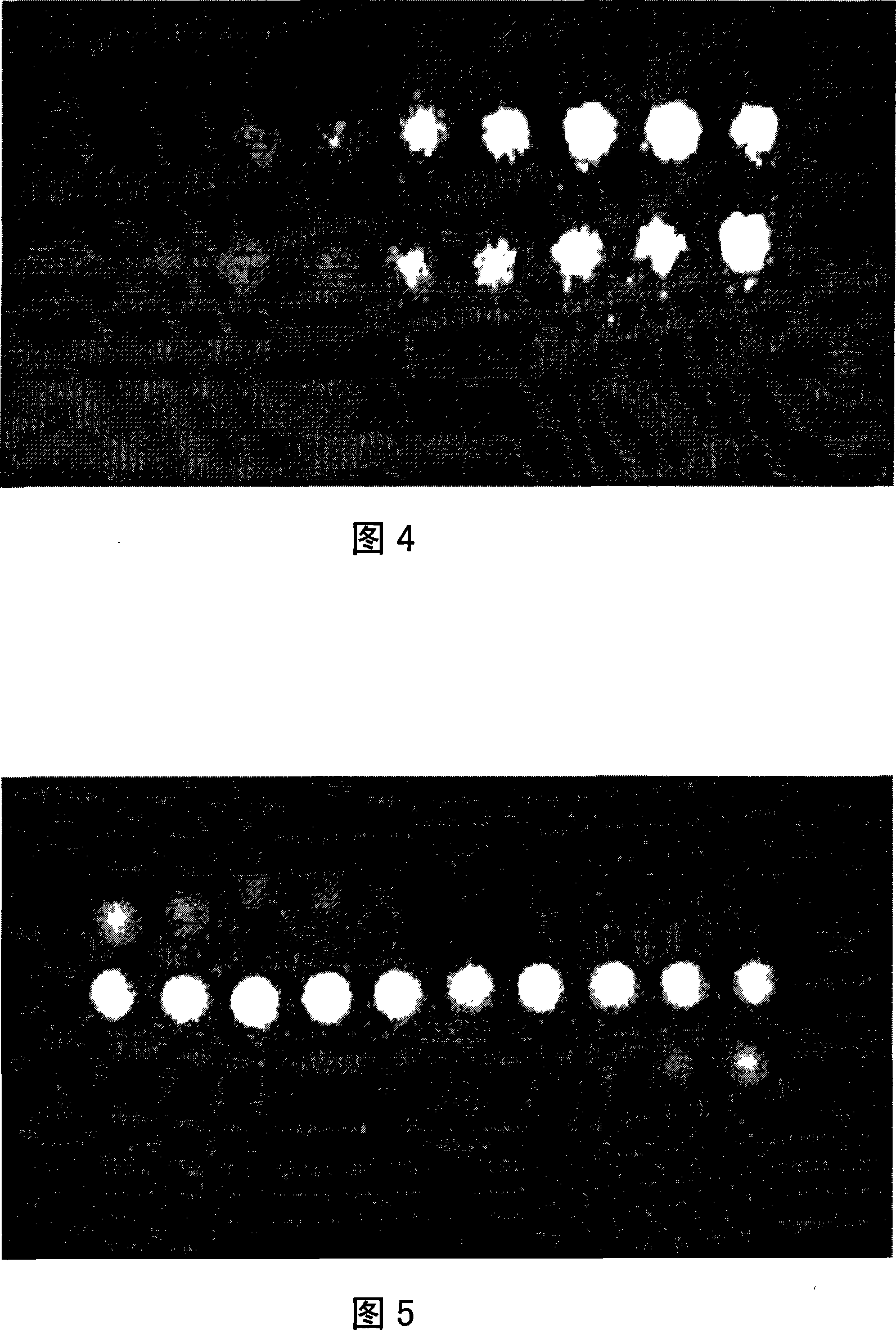
[0018] According to the aforementioned requirements, 101 plastic optical fibers with a diameter of 40 μm (refractive index is about 1.59) were selected. If the length difference of optical fibers is set as 2mm, the time interval is 10ps; the first optical fiber (the shortest one) is 200mm long, and from the second onwards, each fiber is 2mm longer than the previous one, and the 101st optical fiber (the longest one) ) length 200+200=400mm; one end of the optical fiber head is randomly and evenly arranged into a circle of Φ3mm, and fixed as the input end; the output end is arranged in the order of short and long in a helical array fixed from the inside to the outside, and the outer dimension is a circle of Φ5mm. The light spot of this ruler is 101. Theoretically, it can measure the gate shutter time in the range of 10ps-1ns, with an accuracy of 10ps. For example, 91 light spots are measured (the 91 light spots are preferably caught in the middle position of the light spot array...


PUM


Abstract

The invention discloses a photoelectric image strobe shutter time set up measuring method and a device. The invention adopts an element which can display optical signal arrays in order in a flat panel at fixed time difference to ensure the optical signal arrays flat images focus on a photocathode face of an image converter and a strobe shutter under test is arranged between the image converter and the image plane of the image converter. When ultra-short optical pulse signal is input into the photoelectric signal array element through the input terminal, optical pulse signals are displayed in the order of the arrays at the output terminal at fixed time difference, the strobe shutter under test is opened at the moment. Then the optical pulse signals displayed orderly at fixed time difference are imaged and recorded, the open time of the strobe shutter under test can be determined according to the number of light spots recorded. Thus, strobe shutter time set up can be measured. The element-the length differences between each two adjacent optical fibers in an ultra-fast optical yard-stick are the same. When ultra-short optical pulses shine on the input terminal plane, optical pulse signals are displayed at fixed time difference in the order of the arrays. Compared with the prior art, the measuring method and device of the invention have the advantages of high accuracy, better reliability, good repeatability, high measurement efficiency, easy operation and low cost.

Description

technical field [0001] The invention is an improvement to a photoelectric image gating shutter time calibration measurement method, specifically relates to the precise calibration of the gating shutter time of a variable image tube framing camera, and belongs to the technical field of photoelectric instrument measurement. Background technique [0002] Nanosecond (10 -9 seconds) and picoseconds (10 -12 Seconds) precise calibration measurement of gated shutter time is a very important but very difficult task. The measurement of electrical pulses can be carried out with the help of a high-frequency oscilloscope, but it is coupled to the actual load of the variable image tube framing camera, and it is necessary to precisely calibrate and measure the time of the gate shutter. There are not many technical methods available at present, and most of them adopt the F-P standard With (Fabry-Perot etalon) method for generating optical pulse trains. It is to introduce a single optical...

Claims


Application Information

Patent Timeline
Patent Type & Authority Applications(China)
IPC IPC(8): G01M11/00G01M11/02
Inventor 彭文达牛丽红刘进元李骊欧均富袁华涛
Owner SHENZHEN UNIV
Why Eureka
Eureka Blog
Learn More