Method of producing electrolytic capacitor

A technology for electrolytic capacitors and manufacturing methods, which is applied in the direction of electrolytic capacitor manufacturing, electrolytic capacitors, capacitor manufacturing, etc., and can solve the problems of increased leakage current, inability to fully suppress the cracking of the dielectric layer, and the crystallization of the dielectric layer

Inactive Publication Date: 2008-01-30
SANYO ELECTRIC CO LTD
View PDF3 Cites 0 Cited by
  • Summary
  • Abstract
  • Description
  • Claims
  • Application Information

AI Technical Summary

Problems solved by technology

[0005] However, even in the above-mentioned solid electrolytic capacitor in which a dielectric layer having a niobium oxide layer and a niobium nitride region is provided on the surface of the anode using niobium, it is not possible to sufficiently suppress the loss of the dielectric layer during a heat treatment process such as a resolubility process. cracks or crystallization of the dielectric layer, there is still the problem of increased leakage current

Method used


Image

  • Method of producing electrolytic capacitor
  • Method of producing electrolytic capacitor
  • Method of producing electrolytic capacitor

Examples


Embodiment Construction

[0026] Hereinafter, the present invention will be described in more detail based on specific embodiments. However, the present invention is not limited to the following embodiments, and can be implemented with appropriate changes within a range that does not change the gist.

[0027] (experiment 1)

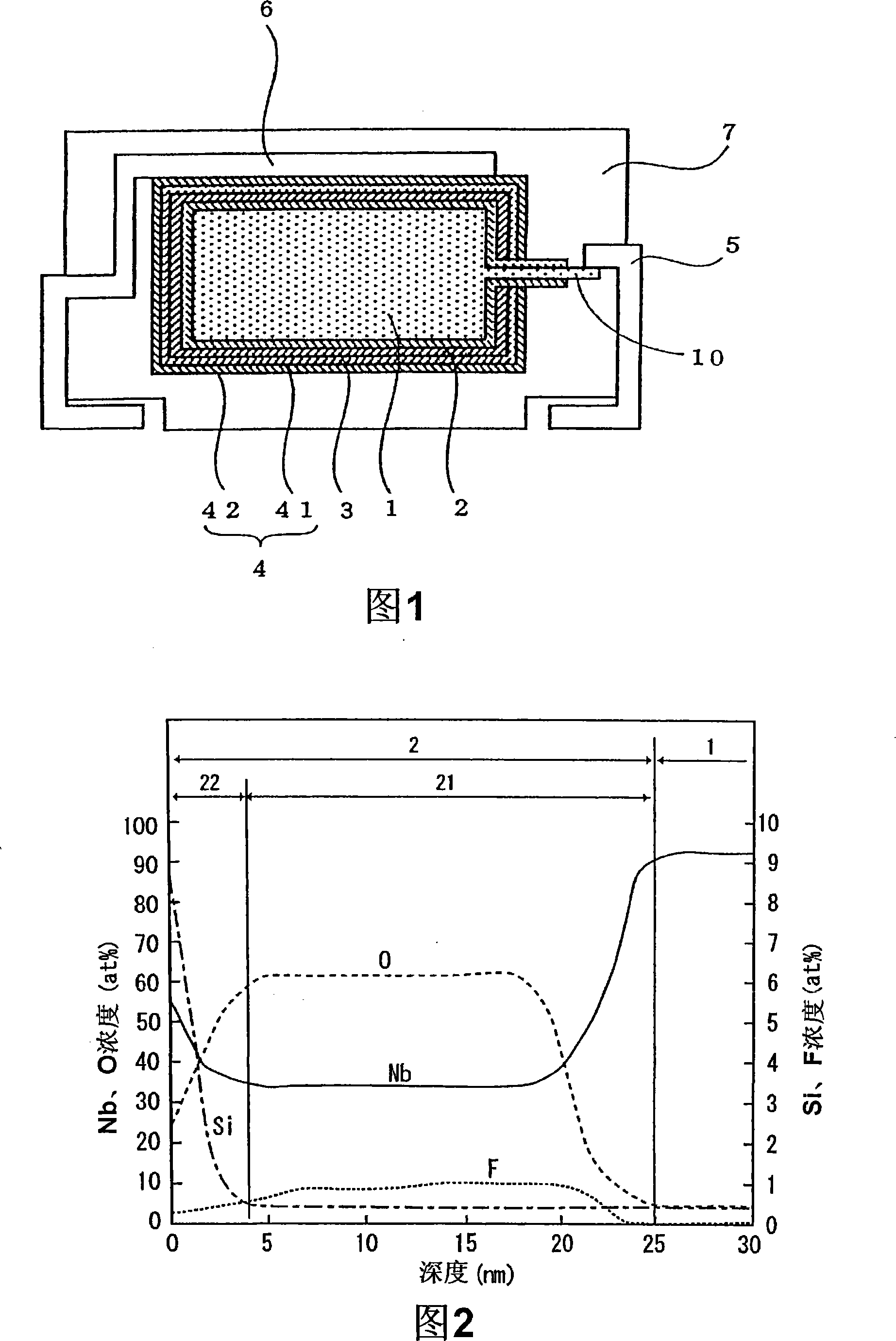
[0028] In Experiment 1, the anode was anodized using an ammonium hexafluorosilicate aqueous solution, thereby forming a dielectric layer. FIG. 1 is an explanatory cross-sectional view of a solid electrolytic capacitor fabricated in Experiment 1. FIG. Referring to FIG. 1 , a method for manufacturing the solid electrolytic capacitor produced in Experiment 1 will be described.

[0029] In Experiment 1, niobium metal powder with an average particle diameter of 2 μm was first sintered to produce an anode 1 made of a porous sintered body of niobium, and a lead wire 10 made of tantalum metal was extended from the anode 1 . Among them, niobium is an example of the "valve action metal" i...


PUM

PropertyMeasurementUnit
depthaaaaaaaaaa

Abstract

Provided is a method of producing an electrolytic capacitor being higher in capacitance, lower in leakage current, and difficult to deteriorate these properties even when processed in a heat-treatment process such as reflow soldering process. In the method of producing a solid electrolytic capacitor, firstly, an anode containing a valve metal is prepared. Then, the anode is anodized in an aqueous solution of 0.1% by weight of ammonium hexafluorosilicate to form a dielectric layer on the surface of the anode. An electrolyte layer of polypyrrole is formed on the dielectric layer, and further a cathode is formed on the electrolyte layer. Subsequently, an anode lead is connected to the anode and a cathode lead is connected to the cathode, and these are covered with a resin layer of an epoxy resin.

Description

technical field [0001] The present invention relates to a method of manufacturing an electrolytic capacitor. Background technique [0002] Generally, a solid electrolytic capacitor includes: an anode composed of valve metals such as titanium, niobium, and tantalum, or an alloy mainly composed of these valve metals, and a dielectric formed on the surface of the anode composed of oxides of these valve metals layer, a solid electrolyte layer made of conductive oxide or conductive polymer formed on the dielectric layer, and a cathode made of carbon layer and silver paint layer formed on the solid electrolyte layer. Here, the dielectric layer is formed by anodizing the anode in an electrolytic solution such as an aqueous phosphoric acid solution (for example, refer to JP-A-6-151258 and JP-A-2004-18966). [0003] However, the above-mentioned dielectric layer made of an oxide of a valve metal is easily affected by heat. In particular, the dielectric layer formed by anodizing an an...

Claims


Application Information

Patent Timeline
Patent Type & Authority Applications(China)
IPC IPC(8): H01G9/00H01G13/00H01G9/04
CPCH01G9/07H01G9/15H01G9/0032
Inventor 高谷和宏饭田贵久梅本卓史野野上宽
Owner SANYO ELECTRIC CO LTD
Why Eureka
Try Eureka