Mascara brush

An eyelash brush and eyelash technology, which is applied in the field of eyelash brushes, can solve the problems of not being able to comb the eyelashes well, the teeth of the plates cannot be close together, and the eyelashes stick together, etc., and achieve the effect of low cost, simple manufacture, and good curling degree

Inactive Publication Date: 2008-01-30
AMOREPACIFIC CORP
View PDF2 Cites 0 Cited by
  • Summary
  • Abstract
  • Description
  • Claims
  • Application Information

AI Technical Summary

Problems solved by technology

However, since the center of all plate-tooths is the same as the center of the brush shaft, and all the plate-tooths are the same size, the eyelashes are combed upwards, and when the eyelashes are brushed upwards with a mascara-filled mascara brush, the plate-tooths Does not fit close to the lashes, so not only will the lashes not be combed or curled to the tips, but the lashes may stick together

Method used


Image

  • Mascara brush
  • Mascara brush
  • Mascara brush

Examples


Embodiment Construction

[0022] The mascara brush of the present invention will be described in detail below in conjunction with the accompanying drawings.

[0023] The accompanying drawings of the present invention are illustrated to make the above and other objects, features, advantages and embodiments of the present invention more comprehensible, but the present invention is not limited to the forms in these drawings.

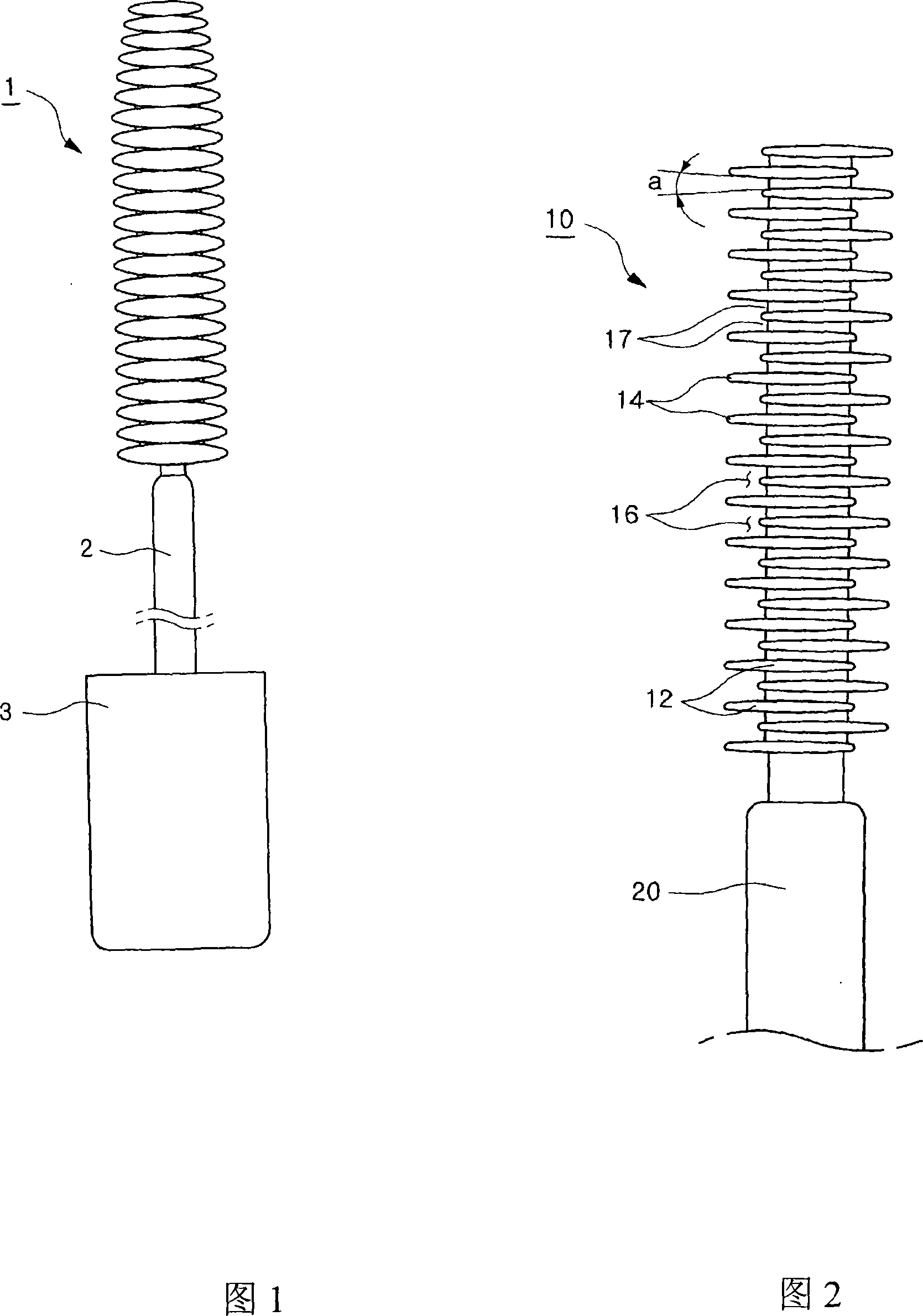
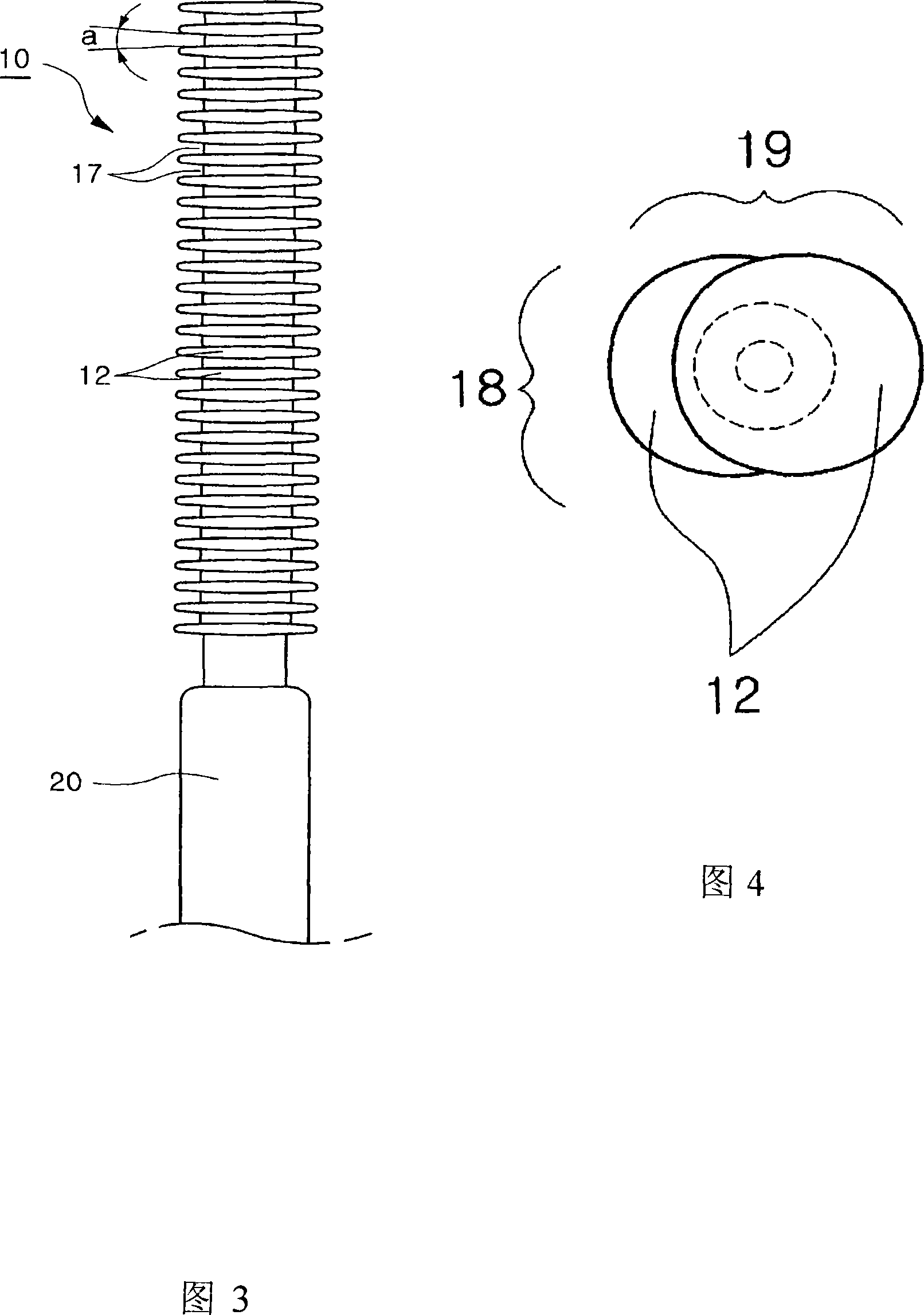
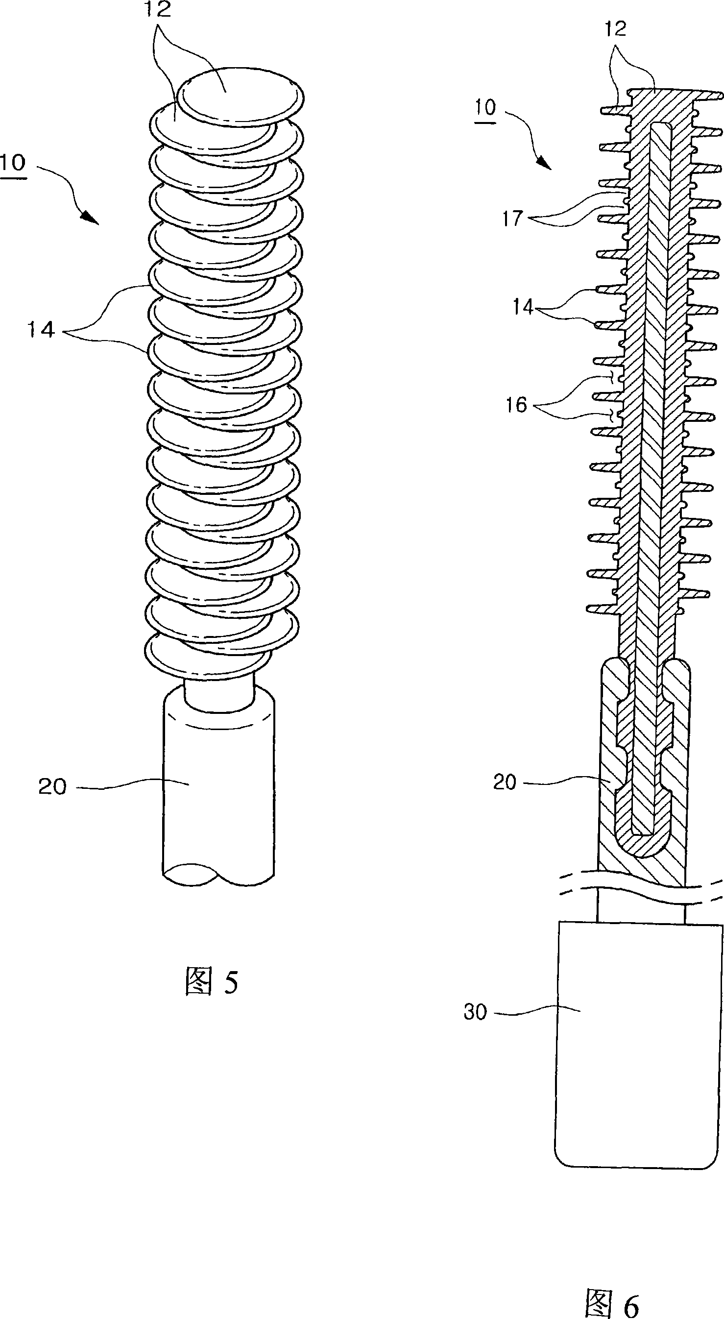
[0024] Fig. 2 is the front view of the mascara brush according to one embodiment of the present invention, Fig. 3 is the side view of the mascara brush according to one embodiment of the present invention, Fig. 4 is the plane view of the mascara brush according to one embodiment of the present invention, FIG. 5 is a perspective view of a mascara brush according to one embodiment of the present invention, and FIG. 6 is a vertical sectional view of the mascara brush according to one embodiment of the present invention.

[0025] As shown in the figure, the present invention provides a ...


PUM

PropertyMeasurementUnit
Slopeaaaaaaaaaa

Abstract

The invention discloses a disc-shaped mascara brush, which is used for using mascara to make up eyelashes. It has a brush part integrally formed at the end of the brush shaft. , the brush part is in the shape of stacking discs at the end of the brush rod. The mascara brush has an integrally formed brush part. Both sides around the axis of the brush bar.

Description

technical field [0001] The invention relates to a mascara brush, which is used for mascara to make up eyelashes, in particular to a disc-shaped mascara brush, the brush part of which is located at the end of the brush rod and stacked continuously in a zigzag shape. Background technique [0002] In general, mascara cosmetics include a container for storing mascara with a certain viscosity and color, a mascara brush for applying the mascara contained in the container to eyelashes, and a cap fitted to the mascara brush. [0003] There are two traditional types of mascara brushes; brushes with plastic bristles wrapped around two metal wires and disc-shaped mascara brushes with the brush portion at the end of the shaft like many plates stacked on top of each other in succession. [0004] Because traditional brushes are made by curling plastic bristles around metal wires, manufacturing is complicated, productivity is low, and quality assurance is difficult. Although the disc masc...

Claims


Application Information

Patent Timeline
IPC IPC(8): A45D34/04
CPCA46D1/00A46B9/021A46D1/0253A45D40/262A46B2200/106A45D34/04A45D40/26
Inventor 克里斯托弗·鲁博斯
Owner AMOREPACIFIC CORP
Why Eureka
Try Eureka