Ankle foot orthosis

A technology of ankle-foot orthosis and orthosis, which is applied in medical science and other fields, can solve the problems of expensive purchase and expensive manufacture

Inactive Publication Date: 2008-01-30
罗伯特·约翰·瓦特
View PDF1 Cites 16 Cited by
  • Summary
  • Abstract
  • Description
  • Claims
  • Application Information

AI Technical Summary

Problems solved by technology

The effect of this is ultimately to make orthotics more expensive

Method used


Image

  • Ankle foot orthosis
  • Ankle foot orthosis
  • Ankle foot orthosis

Examples


Embodiment Construction

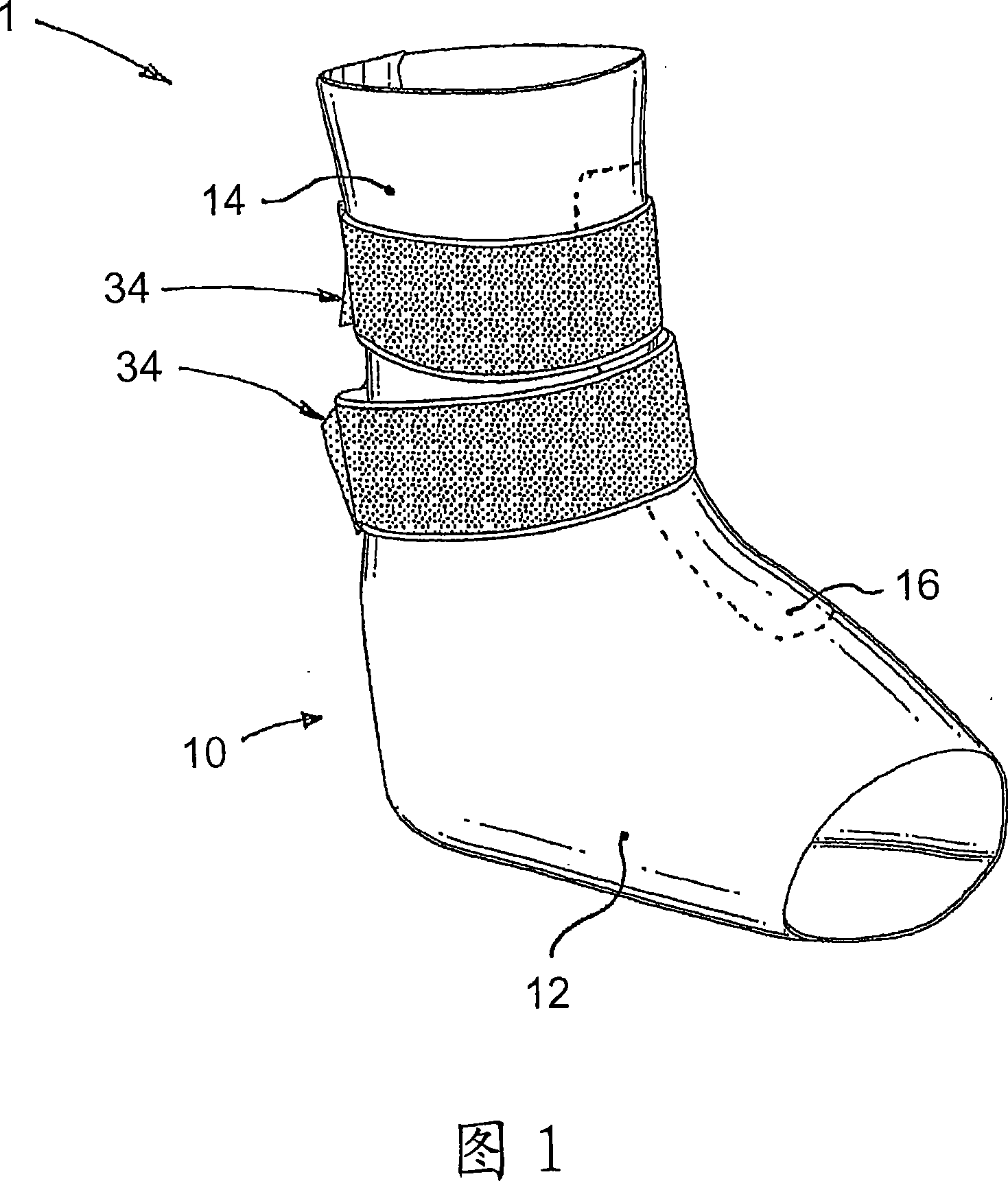
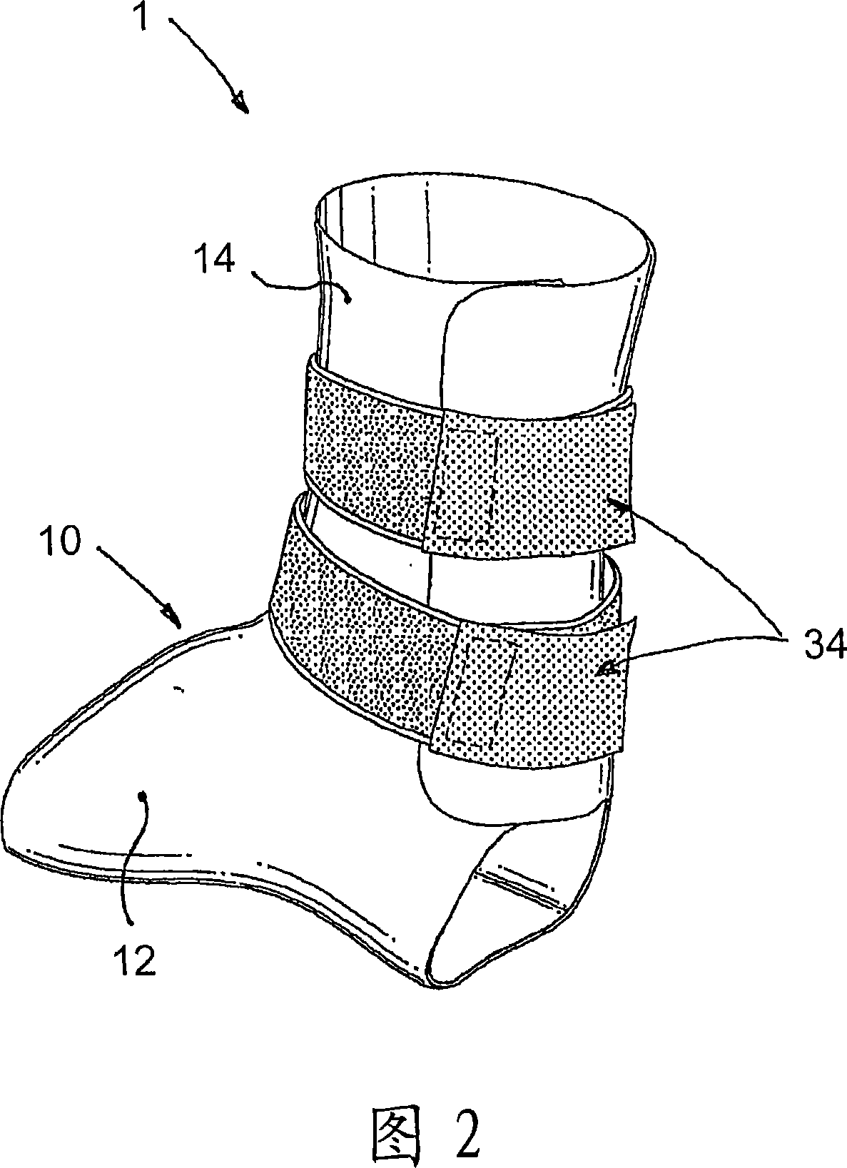
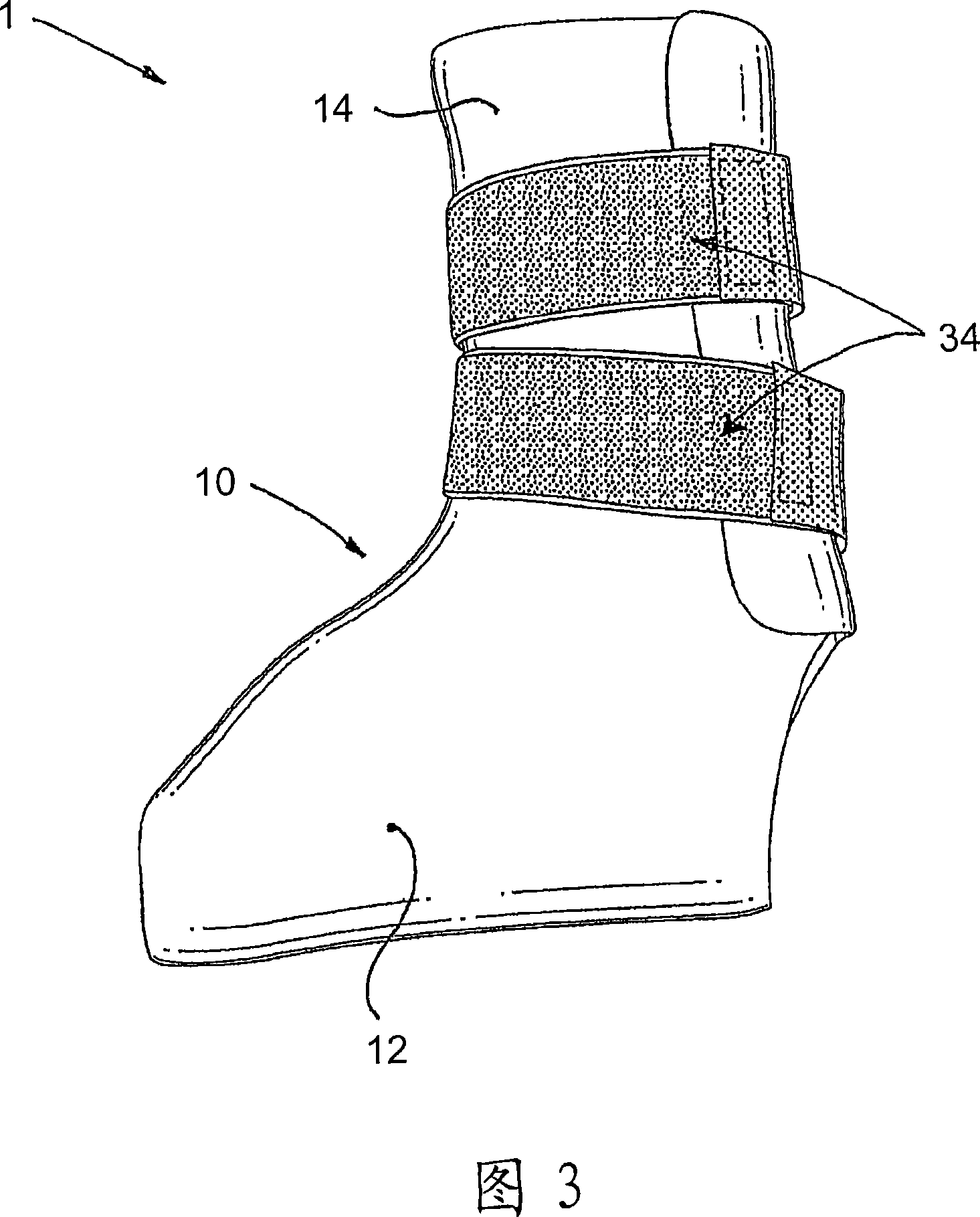
[0028] Figure 1 is a perspective view of an embodiment of the invention in a closed configuration. The orthosis 1 shown in Figure 1 is shown as it is worn by the patient (the patient's foot, ankle and lower leg are omitted for clarity), although it is worth noting that the orthosis is elastic when not being worn by the patient. It is also sufficient for it to retain its three-dimensional shape (as generally shown in Figure 1).

[0029] The orthosis comprises an orthopedic structure 10 consisting of a first tubular portion 12 and a second tubular portion 14 . The first and second tubular sections are continuous and in most cases the second tubular section 14 is integrally formed with the first tubular section 12 . The first and second tubular portions are set at an angle to each other so as to provide, at least in use, a generally L-shaped internal cavity 16 ( FIG. 4 ), which is sized to accommodate the orthosis in use. the patient's foot, ankle and lower leg (not shown), and...


PUM


Abstract

A preferred embodiment of the invention provides an ankle-foot orthosis (1) for resisting plantarflexion of a patient's foot, comprising a resiliently flexible sock-like orthotic structure (1) formed of first (12) and second (14) tubular sections set at an angle to one another, wherein the second tubular section is capable of being opened for insertion of the patient's foot and lower leg into respective ones of said first and second tubular sections, the orthosis further comprising at least one closure member (34) that can be passed round at least part of the periphery of the second tubular section and secured in place to urge the second tubular section towards a closed position in which the second tubular section is closely fitted to the lower leg of the patient.

Description

technical field [0001] The present invention relates to ankle foot orthoses. Background technique [0002] An orthosis is a mechanical device that exerts force on a patient's limb and can be used for many different purposes. For example, an orthosis may be used for supportive, functional, corrective or protective purposes, or indeed a combination of these purposes. [0003] Ankle-foot orthoses are generally used to provide protection to a patient's ankle and foot while providing support against hyper-plantar flexion (or more colloquially "foot drop"). Plantarflexion of the foot is a medical condition caused by disease, trauma, or a congenital abnormality. Patients infected with this condition often have difficulty walking because the patient's foot tends to droop when lifted off the ground, so the patient typically has to lift the foot higher than it should to avoid tripping. It is also not uncommon for patients to have problems during the swing phase of the gait cycle, s...

Claims


Application Information

Patent Timeline
IPC IPC(8): A61F5/01
CPCA61F5/0111
Inventor 罗伯特·约翰·瓦特
Owner 罗伯特·约翰·瓦特
Why Eureka
Try Eureka