Constant temperature oven

A constant temperature tank and tank body technology, applied in the field of constant temperature tank, can solve the problems of large maximum temperature difference and temperature fluctuation, unreasonable structure of constant temperature tank, unsatisfactory use effect, etc., achieve maximum temperature difference and small temperature fluctuation, simple structure , temperature stability and uniform effect

Inactive Publication Date: 2008-02-06
陈坚
View PDF0 Cites 14 Cited by
  • Summary
  • Abstract
  • Description
  • Claims
  • Application Information

AI Technical Summary

Problems solved by technology

The structure of some existing constant temperature tanks is not reasonable enough. For example, the tank body of a constant temperature tank is provided with two ring-shaped cavities, the upper and lower ends of the cavities are opened with circulation channels, and the middle cavity is used as the working area. The bottom of the middle chamber is equipped with a motor and a stirring paddle, and the liquid medium in the tank forms a circulation from the middle chamber to the chambers on both sides to achieve uniform temperature
The disadvantage is that the maximum temperature difference and temperature fluctuation in the tank are relatively large, and the use effect is not ideal.
Moreover, the small cavity in the middle is used as a test work area. If the tested thermometer falls on the stirring paddle, it will damage the stirring paddle.

Method used


Image

  • Constant temperature oven

Examples


Embodiment Construction

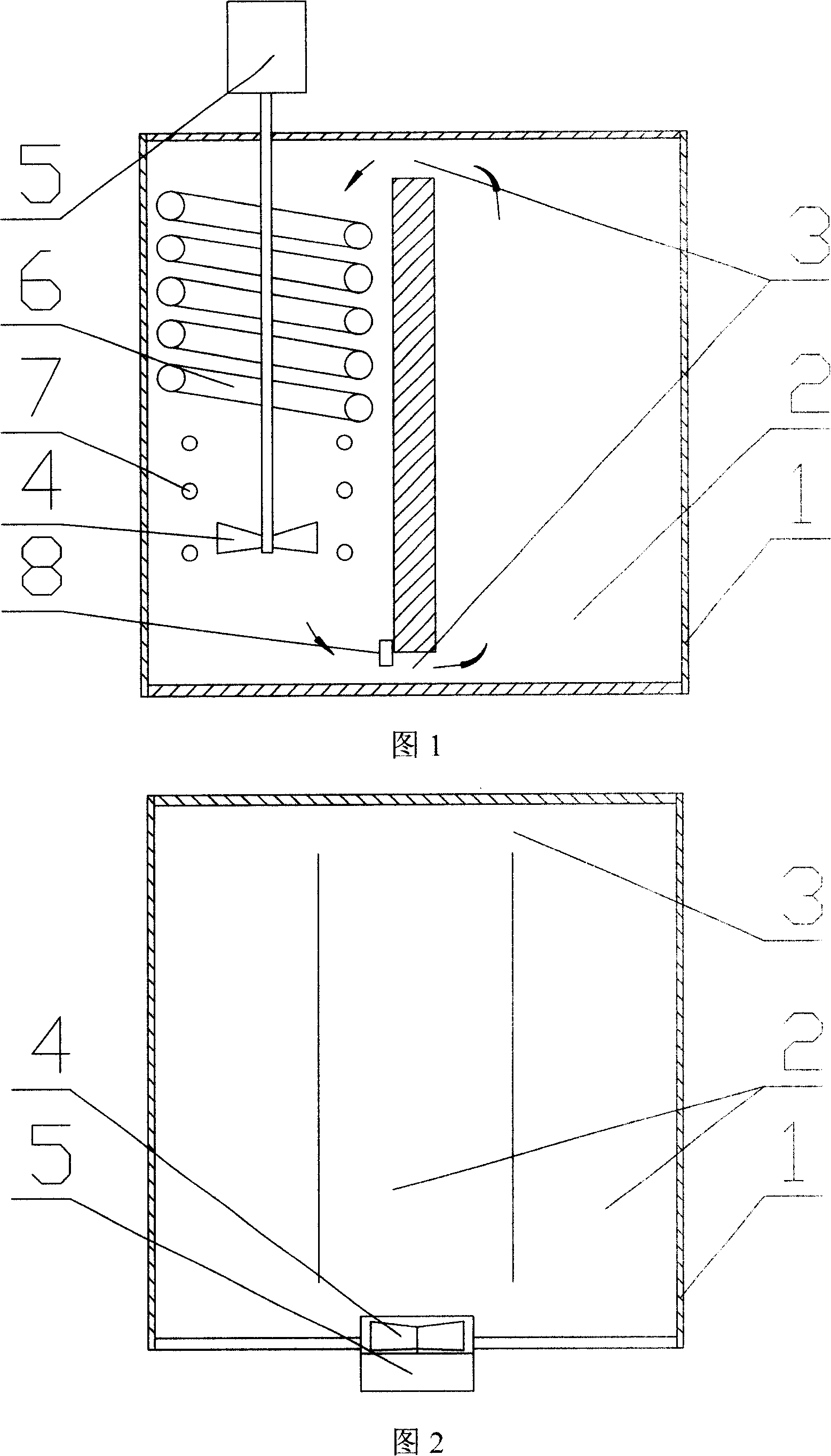
[0012] The embodiment of the present invention: the tank body (1) of the thermostatic bath is made of stainless steel, the tank body (1) is divided into two left and right cavities (2), and a circulation is left between the upper and lower ends of the cavities (2) In the channel (3), a stirring paddle (4) is installed in one of the cavity (2), the stirring paddle (4) is connected to the motor (5), and the motor (5) is installed above the tank (1), in the cavity (2) Install spirally arranged pipes (6) inside, and pipes (6) are connected to the refrigerator for cooling the liquid medium, and a heater (7) is installed in the same cavity (2) to heat the liquid medium. A temperature-sensitive platinum resistor (8) is installed at the bottom of the cavity (2) for temperature verification.

[0013] The liquid medium is water or oil. The temperature control system controls the operation of the refrigerator or heater (7) according to the set temperature and the temperature measured by the ...


PUM


Abstract

The present invention discloses a constant-temperature groove, which comprises a groove body (1) and is characterized in that the groove body (1) is divided into 2 cavities (2) including a left one and a right one, wherein circulation channels (3) are arranged on the upper end and the lower end between the cavities (2), a stirring oar (4) is arranged inside one of the cavities (2) and connected with an electrical machine (5). The groove body provided by the present invention is divided into 2 cavities, one of which is adopted as the working area, and the other is provided with the stirring oar inside to form a single circulation of the medium, thereby having simple structure, higher technical standard, and the temperature which is much more stable and even. As proved by the test carried out by National institute of metrology, the technical index of the present invention is superior to or meet the national standard, meanwhile the present invention adopts the stirring on the lateral of the working area, thereby preventing the stirring oar of the constant-temperature groove from being damaged by the fallen thermometer used to measure the temperature. The present invention has the advantages of a simple structure, small fluctuation of both the temperature and the maximum temperature difference, and the technical index superior to the national standard, etc.

Description

Technical field: [0001] The invention relates to a constant temperature bath for constant temperature experiments, in particular to a constant temperature bath with uniform temperature field. Background technique: [0002] The function of the thermostatic bath is to make the temperature in the working area stable and uniform by controlling the temperature of the liquid medium in the bath, which is used to calibrate the thermometer in the working area. The structure of some existing thermostatic baths is not reasonable enough. For example, the bath body of a thermostatic bath is provided with two annular cavities, the upper and lower ends between the cavities are provided with circulation channels, and the middle cavity is used as the working area. The bottom of the middle cavity is provided with a motor and a stirring paddle, and the liquid medium in the tank forms a circulation from the middle cavity to the cavities on both sides to achieve the purpose of uniform temperature. Th...

Claims


Application Information

Patent Timeline
Patent Type & Authority Applications(China)
IPC IPC(8): B01L7/02
Inventor 陈坚
Owner 陈坚
Why Eureka
Try Eureka