
Powder feeder for manufacturing function gradient element or material

A functional gradient, powder feeder technology, applied in metal material coating process, conveyor, mechanical conveyor, etc., can solve the problems of difficult control of powder feeding amount, screw stuck, poor powder discharge, etc., to achieve powder feeding The effect of continuous and easy control, increasing conveying distance and long powder feeding distance

Inactive Publication Date: 2008-02-06
HUAZHONG UNIV OF SCI & TECH
View PDF2 Cites 11 Cited by
  • Summary
  • Abstract
  • Description
  • Claims
  • Application Information

AI Technical Summary

Problems solved by technology

The direct gravity powder feeding device controls the amount of powder by controlling the opening size of the lower end of the powder storage container (powder hopper), and uses the gravity of the powder itself to quantitatively transport it to the forming molten pool. This method is not easy to control the powder feeding amount and cannot be accurately measured. Poor degree, poor powder discharge
The scraper-type powder feeding device uses a scraper to discharge powder gradually. It has a large volume and a complicated structure. During the conveying process, it has to pass through a large powder bin, which is easy to accumulate powder. The natural cone formed by the powder on the powder feeding disc under the device can control the powder feeding amount by changing the speed of the powder feeding disc. Since it is difficult to ensure the flatness of the powder feeding disc during installation and operation, the amount of powder sent not well controlled
[0003] The Chinese patent CN2584340Y applied for in 2002 announced a powder feeder for laser cladding. It adopts a screw powder feeding method. During use, the screw rod slides and cooperates with the inner wall of the powder groove. It is easy to cause screw jamming during the powder feeding process, which will cause powder feeding interruption and force the processing to stop; Chinese patent CN2555103Y announces a laser coated powder feeder, which uses a drum as the powder feeding metering element, and the outer surface of the drum It is engraved with uniform grooves, and the drum rotates under the drive of the motor. The grooves quantitatively extract powder from the left powder storage bin. Adjustable quantitative powder feeding can be realized by adjusting the rotating speed of the drum and the material level height of the powder storage bin.

Method used


Image

  • Powder feeder for manufacturing function gradient element or material

Examples


Embodiment Construction

[0016] The present invention will be further described below in conjunction with the accompanying drawings and embodiments.

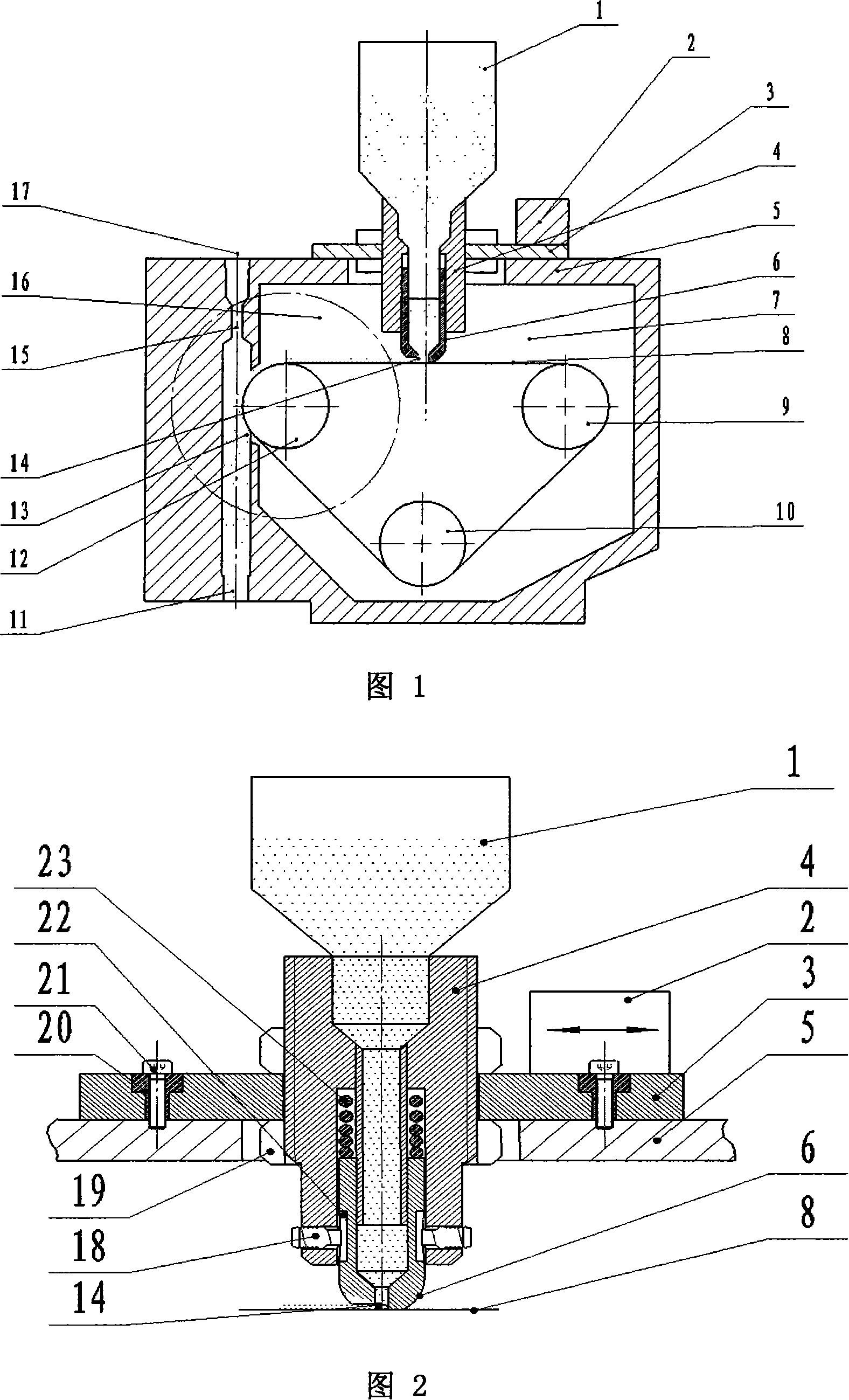
[0017] As shown in Fig. 1, driving wheel 12, driven wheel 9, tension pulley 10 and synchronous powder feeding belt 8 are installed in the powder feeding cavity 7 of housing 5 of the present invention, and synchronous powder feeding belt 8 is composed of driving wheel 12 and driven wheel Driven by 9 and tensioned by the tensioning wheel 10, there is a powder feeding gap 13 on one side of the powder feeding chamber 7, which communicates with the air supply and powder outlet channel on the side of the housing; the opening on the air supply and powder outlet channel is the powder feeding gas inlet 17 1. The lower opening is the powder outlet 11, and the inner diameter of a part of the upper section of the air supply and powder outlet channel is smaller than the inner diameter of other parts, forming a powder delivery gas acceleration hole 15.

[0018] As sh...


PUM


Abstract

A powder feeder for manufacturing functionally gradient parts or materials belongs to a powder feeding equipment of powder material and can feed powder continuously and easily with powder-feeding amount controllable, powder-feeding distance far and powder-feeding quantity precise in micro amount, as the object of the present invention requires. A casing powder-feeding cavity of the present invention is provided with a driving wheel, a driven wheel, a tightening wheel and a synchronous powder-feeding belt; a powder-feeding notch at one side of the powder-feeding cavity communicates with a gas-sending powder discharging passage of the casing; a bottom plate with a fixed vibrating device is arranged on the casing via mounting screws and elastic rings; a powder-precipitating adjusting device is fixed to the bottom plate; a powder storage barrel is arranged at the upper section of the powder-precipitating adjusting device, and the low section of the powder-precipitating adjusting device is provided with a powder-precipitating tube; the powder-precipitating tube and the powder-storage barrel communicate via a round tube sleeved with a spring; the lower part of the powder-precipitating tube and the end part of a powder-guiding groove keep in contact with the synchronous powder-feeding belt; the opening direction of the powder-guiding groove is as same as that of the rotation of the synchronous powder-feeding belt. The present invention has the advantages of compact structure, uniform and continuous powder feed, long powder-feeding distance as well as precise micro-amount powder feed realization, and can meet the manufacture requirements of various functionally gradient parts or materials.

Description

technical field [0001] The invention belongs to a powder feeder for powder materials, in particular to a powder feeder for manufacturing functionally gradient parts or materials. Background technique [0002] Functionally graded parts or materials are a new type of composite parts or materials developed to meet the needs of new materials in high-tech fields and to meet the repeated normal work in extreme environments (ultra-high temperature, large temperature drop, etc.). The two sides of the composite part or material are composed of materials with different properties, and the middle part is to continuously change the composition and structure of the two materials, so that the internal heterogeneous material interface of the composite part or material disappears, so that the function corresponding to the composition and structure can be obtained. The non-homogeneous material parts or composite materials that change slowly due to the change of different materials, thereby e...

Claims


Application Information

Patent Timeline
Patent Type & Authority Applications(China)
IPC IPC(8): C23C24/00B65G37/00
Inventor 张海鸥邹海平王桂兰
Owner HUAZHONG UNIV OF SCI & TECH
Learn More